
Theatre Lighting Intro: Software 1
[Theatre Lighting Contents Page]In Hardware 2: Principles of Operation of DMX Control, we explored the basic means of operation of the DMX signalling protocol now commonplace in the theatre industry. Having now an understanding of its main principles of operation and physical implementation, and having also explored some more advanced theatrical devices such as intelligent light fixtures and smoke/pyrotechnic machines, we can now proceed to discussing the exact signalling processes employed by the DMX512 protocol. It is important to grasp these since they outline the means by which one may correctly configure a DMX daisy chain (one "universe").
It was discussed, in Hardware 2: Principles of Operation of DMX Control, how the DMX protocol allows for the dedicated control of up to 512 individual channels through only one cable. This is different to the earlier analogue standards which would require an individual wire for each channel of control (such as the multi-core analogue cables used on older dimmer packs to connect directly to slider potentiometers on a simple console).
As also mentioned in Hardware 2, the DMX protocol sends to each channel a binary-encoded number between 0 and 255. When controlling a fixture connected to a dimmer pack, 0 would correspond to 0% intensity (off) and 255 would correspond to 100% intensity (fully on), with any value between stipulating the proportional intensity of the dimmed light. The correct dimmer pack decodes the multiplexed DMX signal such that each of its channels changes to the correct percentage intensity based on the 0-255 signal on the control address corresponding to each channel.
Each channel of control outputted from the DMX console is assigned a unique address between 1 and 512. This address is independent to the actual numerical signal value (0-255) associated with that control channel: the address does not dictate the numerical 0-255 signal value - it simply serves as a transmission identifier. With the example of standard six-channel dimmer packs, the user selects which six addresses the dimmer pack should check, or "sample", from the data emanating from the console. Let us assume that the console is outputting the following data to the first eight DMX addresses:
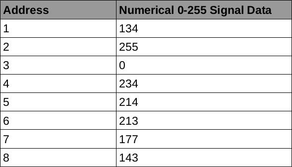
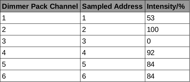
If a dimmer pack connected to the tabulated DMX universe is set to sample the first six addresses for its channels of dimmer control. These dimming channels would be set to the following percentage levels (calculated based on the 0-255 signal proportion from above):
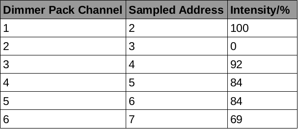
Similarly, if the dimmer pack were set to sample DMX addresses 2 to 7 inclusive, its channels would be set at the following percentage intensities:
By daisy-chaining multiple dimmer packs, each set to sample a different address range, up to 512 channels of dimming can be controlled over a single DMX cable. As soon as a signal value on a particular address is changed by the console, the dimmer channel corresponding to that address adjusts in intensity accordingly. Most digital dimmer packs contain a small digital control module such as that annotated on the photograph of a Zero88 Betapack 3 in H3.5 - Theatrical Dimmer Packs. This control module allows for one to set the DMX start address - the first DMX address sample point from which the dimmer pack will inclusively sample the data of six consecutive individual addresses for each of its six output levels. For example, if one sets the DMX start address as 7, the dimmer pack will sample DMX addresses 7 to 12 inclusive for its channels 1 to 6 respectively. Older DMX-enabled dimmer packs may use a component such as that shown below:
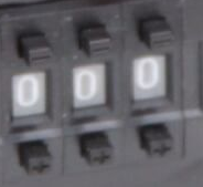
Here, the black up/down buttons above each digit allow for the mechanical selection of a three-digit number as the start address. By pushing the buttons, new digits mechanically come into view and the internal circuitry is reconnected for a different start address. These selector devices used to be more common on earlier DMX dimmer packs but have now been largely replaced by more robust, easy-to-operate, digital controls.
At this point, one must note that if the DMX start address on a dimmer pack is set to 512, it is likely that this will produce unpredictable incorrect operation because one DMX universe only supports 512 addresses of control; and a start address of 512 would mean that the dimmer pack would attempt to sample addresses 512 to 517 inclusive - a range with five non-existent addresses! Similarly, if any DMX device were set to sample non-existent DMX universe addresses, problems would result. On modern digital dimmer packs, the internal microcontroller may prevent the start address being set to a value nearer than 6 places away from 512. Older mechanical selectors, such as this one, however, may have no provision to detect this type of operator error and therefore rely solely on the knowledge of the user to set the address correctly.
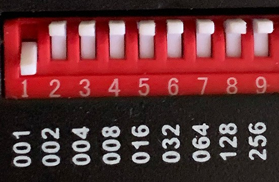
Another two types of mechanical address selector are shown below. On the left selector, one sets the address using three rotary dials (one for units, one for tens, and one for hundreds). On the right selector, the address is set by inputting it in a binary fashion using one little white toggle for each binary digit (units, twos, fours, eights, etc.):

[Top of Section] [Top of Page] [Theatre Lighting Contents]
It may be the case that a DMX network suffers a failure at some point whilst a production is in progress. Such failures typically result from a faulty connection anywhere along the daisy chain and can lead to the subsequent section of the daisy chain simply not receiving a signal. In this instance, it would be highly undesirable for all the lights or devices on this leg of the daisy chain simply to turn off as would typically be the case if a DMX dimmer pack were to stop receiving a data signal. It is therefore the case that many DMX devices (especially those with sophisticated digital interfaces, such as the Zero88 Betapack 3) are equipped with an automatic DMX failure mode in order to maintain some level of lighting even in the absence of an incoming DMX signal. Common failure modes are as follows:
[Top of Section] [Top of Page] [Theatre Lighting Contents]
Since moving-head light fixtures are becoming increasingly common and affordable, it is also the case that it is highly likely that one will need to configure such a fixture. It is therefore of importance to be acquainted with the exact means by which these fixtures are controlled over DMX.
Colour filter (often accomplished by means of a built-in colour scroller; see H5.4 - Colour Scrollers); Dimmer packs are inherently simple devices to control owing to the fact that each channel of dimming requires only one DMX address to control the intensity of the linked fixture. Intelligent moving-head fixtures, however, often have many more parameters which can be controlled from a compatible console. Such parameters include:
As a result of this plethora of controllable features, an individual intelligent fixture receives a direct DMX signal as part of the overall daisy chain (unlike simple dimmed fixtures, each of which receives a modulated power supply from separate banks of DMX-controlled dimmer packs). Furthermore, whereas each dimmed incandescent fixture on a simple dimmer-channel arrangement simply requires one 0-255 digital control address for its intensity, a single intelligent fixture occupies a series of consecutive DMX addresses, each one carrying a different 0-255 binary-encoded control signal to operate a different aspect of the fixture. More information on basic DMX addressing may be found earlier in this section.
NOTE: Do not confuse the way in which dimmer packs and intelligent fixtures sample addresses. Whereas a dimmer pack generally samples a set of six consecutive DMX addresses, one for each incandescent channel of control, an individual intelligent fixture itself requires its own set of addresses.
It is possible to control a rotational parameter (pan/tilt) from a 0-255 address control signal. Such operation may be modelled thus (the "pan" parameter is used as an example here):
Exactly the same procedure may be used for the "tilt" parameter, with the corresponding rotation simply happening on a different axis to that of the "pan" parameter.
The means of control for the "colour filter" parameter is somewhat different. The procedure is explained below for a fixture containing 17 different possible colour filters:
The possible address input signal ranges and their corresponding possible colour filters are shown in the table below:
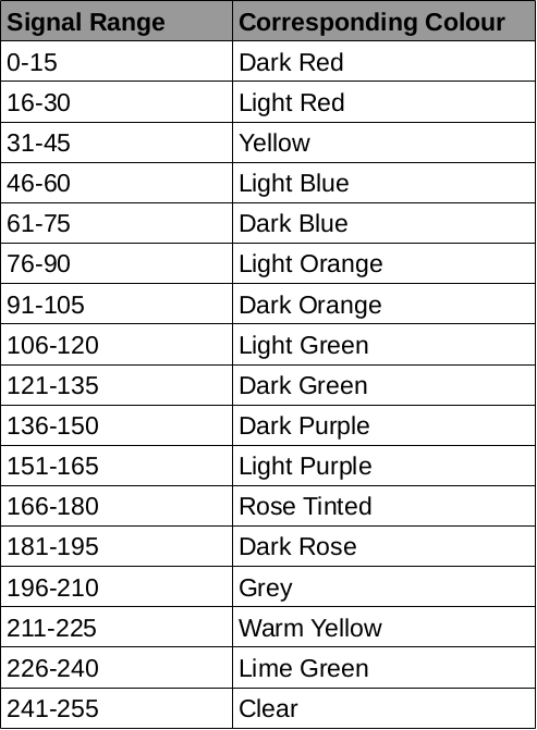
This method of colour control is exactly the same as that utilised by a standalone colour scroller of the sort discussed in H5.4 - Colour Scrollers.
A similar process may be used for the "gobo" parameter. Also, this process may be adjusted for any number of filters or gobos; more filters will result in a smaller numerical signal range per filter whereas fewer filters will result in a greater numerical signal range per filter. The upper limit to the number of possible filters is 256 since only 256 discrete possible values may be taken by the 0-255 control signal on one particular DMX address.
Below is shown a table of these parameters along with their corresponding control addresses. This assumes that the fixture is set to sample DMX address 100 as the start address and that it will therefore sample addresses 100-105 for its parameter data:

Each of these sampled DMX addresses of control carries a dedicated 0-255 control signal from the main console to operate a different aspect of the fixture's functionality. It would be a common arrangement to have, for example, a string of 3 moving lights set at start addresses 100, 105, and 110 (one for each fixture) such that each may receive dedicated control from a central console.
The start address of the fixture can be assigned using integrated controls similar to those used on DMX dimmer packs. It is very common to find a ubiquitous set of digital controls and display of the following kind on an intelligent fixture:

Using the Menu, Up, Down, and Enter buttons, one can adjust the DMX start address of the fixture in conjunction with a number of other user-adjustable settings. Such four buttons are common in some form on nearly all DMX-enabled fixtures and dimmer packs. Here is another such four button module as used on the Zero88 Betapack 3. From this, it is also possible to adjust the DMX failure mode (see S1.2 - DMX Failure Modes):

[Top of Section] [Top of Page] [Theatre Lighting Contents]
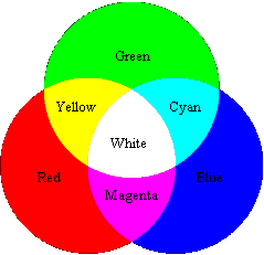
Simple LED fixtures are typically stationary; they cannot be rotated/panned remotely but allow for the remote changing not only of light intensity but of output light colour. This aspect is achieved through the fact that white light is composed of the three optical primary colours: red, green, and blue. By adjusting the respective intensities of three specific overlapping light sources of these colours, any colour of net light output from the visible spectrum may be obtained. Below is shown a useful "overlap diagram" of the three primary colours of light. The three primary circles overlap, giving some examples of the possible colours which may emerge from this mixing process:
An incandescent lamp inherently produces white light: its spectral distribution of constituent colours is even and can therefore be considered to consist of roughly identical proportions of the three primary colours. A filter can be used to restrict the spectral distribution of the light output to a more narrow range of wavelengths (colours of light).
An individual LED, on the other hand, can only produce monochromatic light - that of a single colour. It is therefore the case that LED theatrical fixtures must contain three sets of LEDs, one for each luminous primary colour. Most LED fixtures allow for each primary colour emerging from the fixture to be adjusted individually such that any output colour may result. For example, if white light is desired, the ratio of red:green:blue is set to 1:1:1. However, if pure blue light is desired, this ratio may be adjusted to 0:0:1. More complex ratios may be achieved by adjusting the individual intensities via a DMX control signal from the main console.
An LED fixture contains multiple groups of three primary LEDs clustered in trios behind many small round lenses on the front of the fixture to provide some level of directionality. The red, blue, and green groups behind the lenses are controllable individually.
Below is shown a common LED fixture:

A fixture such as this typically occupies 3 consecutive DMX addresses of control: one for the red component, one for the green component, and one for the blue component. By sending three 0-255 values over these addresses, the colour (and intensity) of overall light output may be altered. For example, if the three addresses (red:green:blue) are carrying the control signals 255:255:255, the output will be white. A lower-intensity white output may be obtained by setting the address signals to 50:50:50. This maintains the same red:green:blue ratio but with an overall lower output level.
Just as with a conventional incandescent fixture, the nominal percentage intensity of each component may be calculated easily by observing the numerical proportion of 255 reached by each component's input signal.
It was mentioned at the start of this section that LED fixtures are typically stationary. However, moving-head LED "wash" fixtures are gaining popularity. Whereas conventional moving-head fixtures typically operate using incandescent or gas discharge lamps (usually in a sealed body), moving-head "wash" lights use the above characteristic layout of LEDs behind lenses such that a somewhat directional wash of light may be produced whose colour and direction may be remotely adjusted.
Below is shown a moving-head LED wash light. It may be clearly seen to be a hybrid of the LED fixture on the previous page and a traditional moving-head light:
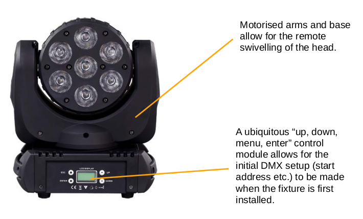
Concerning the DMX addressing of such moving-head LED fixtures, the number of addresses occupied for controlling each aspect of the fixture will obviously be larger than for a simple LED fixture since the pan and tilt parameters may also be controlled. However, whereas it was mentioned in H4.8 - Moving-Head Light Fixtures that a parameter may also correspond to a colour filter, such would not be the case in an LED wash light such as this owing to the ability to control the exact red, green, and blue components of light as discussed above, thus achieving any desired output colour by this means instead.
Below is a table showing the parameters controllable on a simple moving-head LED wash light starting on DMX address 100:
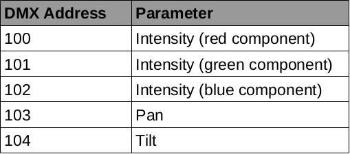
Observing this table, one will notice that there is no "gobo" parameter. Such is very common for LED fixtures owing to the inability of LED light to be specifically focussed - an aspect which is essential if a gobo is to be used. Therefore, if a gobo were used, the silhouette produced would be blurry at best, and most likely unrecognisable. Instead, the light emerges directly through the round translucent plastic lenses visible on the front of the fixture's head.
[Top of Section] [Top of Page] [Theatre Lighting Contents]
Relay modules are not capable of providing dimmed power to the devices under their control but instead simply switch on and off power to their devices. This means that a variable 0-255 incoming control signal on the particular DMX address corresponding to a relay has to be interpreted such that it turns the relay on and off in a binary fashion. The simplest and most common interpretation of an incoming signal for simple relay switches is as follows:
The result of this manner of interpreting the incoming numerical data is that a simple binary switching action may be achieved - exactly as is desirable for the relay. The exact numerical "cut-off" point between the relay being on and off may vary between different devices but generally lies around the halfway point of the possible set of numerical input values.
In H5.2 - Remote Relay Switches, an example was given of a module with 8 individually controllable relays. Such a module would therefore sample eight consecutive DMX addresses, interpreting the numerical value taken by each address signal based on its "cut-off" point.
[Top of Section] [Top of Page] [Theatre Lighting Contents]
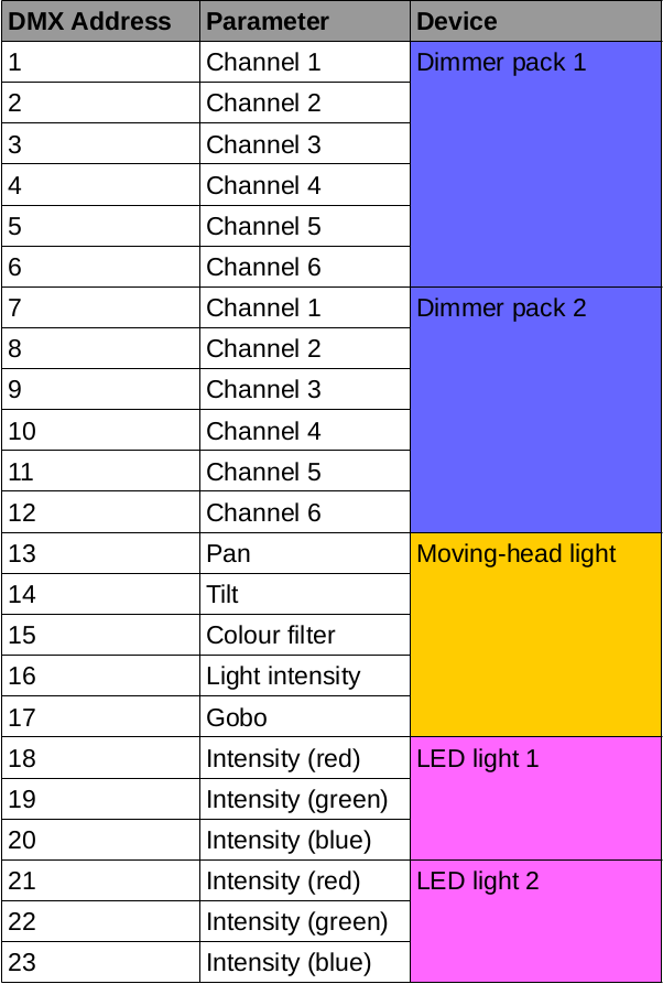
It has been established that an entire chain of DMX devices is termed a "universe". The maximum number of individual controllable addresses available on a DMX universe is 512. Typically, these addresses are split between dimmer packs (for the majority of the lighting fixtures), advanced devices such as smoke machines or relay modules, and intelligent fixtures. Now each intelligent/LED fixture occupies considerably more addresses than a simple dimmed fixture in order to control its many parameters. Whereas a six-channel dimmer pack, sampling six consecutive addresses, may control six individual fixtures, an intelligent fixture may occupy six addresses itself.
A table showing an example distribution of DMX addresses in a small set of theatrical fixtures is shown below. The dimmer packs have their own range of addresses whereas the moving-head lights occupy different ranges. The absence of overlap between any of the devices' address ranges means that each device may receive dedicated control from the central console:
[Top of Section] [Top of Page] [Theatre Lighting Contents]
The DMX512 data transmission protocol has become an incredibly popular universal standard for control of theatrical devices to the extent that traditional analogue dimmer packs are now essentially obsolete. It is also used in venues such as concert/disco halls in order to provide easy control of lighting effects. However, in spite of its advantages in allowing for the creation of an easily controllable daisy chain of devices over a single cable, it also has a number of drawbacks, not least in terms of the potential for failure, often within the cable itself.
Consider the following DMX universe:
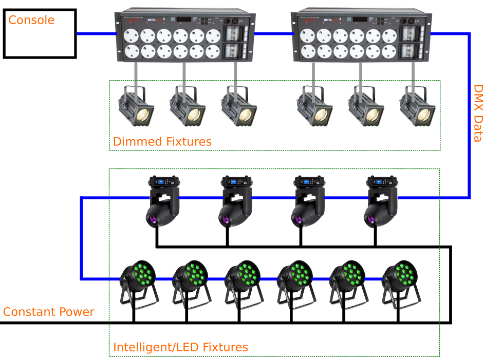
If the DMX data line (blue) were to become broken between the dimmer pack and the first moving-head light, the daisy chain topology means that control would be lost over all the moving-head (middle) and LED (bottom) fixtures. Unfortunately, the potential for breakages in DMX cabling is somewhat large. The main point of breakage is the XLR plug itself: if the cable is pulled hard or strained during the rigging process, the soldered connections inside the plug may pull apart. However, the cabling itself may also become damaged owing to improper handling. Similarly, DMX cabling hard-wired into a venue (for example, embedded within the walls in order to lead discretely from the auditorium console to the backstage dimming equipment) may become damaged during building work. If the damage is subtle, pinpointing the point of breakage along the cable will be a tedious task.
Furthermore, often following physical abuse or wear, DMX data cables may develop internal short-circuits. This means that the cables or plugs themselves start conducting internally at points which should normally be electrically insulated from each other with the result that a cable itself may start producing its own bogus control "data signals" - signals which should normally emanate exclusively from the main console in order to operate the universe's fixtures. The result of such a fault often manifests itself through entirely random flickering/triggering of fixtures. This is of great inconvenience if such a fault occurs during a show but may be dangerous if devices such as pyrotechnic flame throwers are connected to the daisy chain because they could trigger unpredictably and uncontrollably.
A further disadvantage of DMX control manifests itself through the consequences of a failure of a single device on the daisy chain such that its DMX connectors become live at a dangerously high voltage. Since, under normal operation, digitally encoded DMX control signals only operate on ~5v, the application of 240v mains power onto the DMX daisy chain by a faulty device would have the potential to cause major damage to every device on its daisy chain, not to mention the risk of electric shock to anyone touching exposed conductive parts of the DMX cabling/connectors. In order to minimise the likelihood of this occurrence, DMX-enabled devices typically have their internal DMX circuitry very well isolated from any high-voltage components in order to minimise the chance of any sort of dangerous voltage finding its way onto the DMX data line.
It is also the case that it is not only faulty devices which may put dangerously high voltages onto a DMX data line. The non-compliant smoke machines discussed in H2.3 - Physical DMX Connectors also have the potential to cause damage to entire sets of DMX devices if erroneously connected to a DMX universe.
When an electric current flows through any conductor, there is some level of electrical resistance in the conductor itself to the flow of electrons. This means that the energy carried by an electric current will "fade" (reduce in magnitude) by a certain level as it travels along even a simple wire. Since DMX signals utilise low voltages, it is the case that if a daisy chain of very many devices is made, the signal may fade to undetectability owing to the electrical resistance of the connecting wires and the devices themselves. The general rule of thumb is that no more than 32 physical devices should be connected along one DMX daisy chain, regardless of the way in which they are addressed. This could be 32 dimmer packs, 32 intelligent fixtures, or a combination of both. This figure is, however, not definite; in many applications, running more than 32 physical DMX devices along one daisy chain may turn out to work perfectly.
Ordinarily, a DMX universe will contain a linear topology of devices daisy-chained straightforwardly off each other. In the case of a venue based entirely around conventional dimmed fixtures, it is highly unlikely that more than 32 dimmer packs (each dimmer pack is one DMX device, even though it occupies six consecutive addresses for six fixtures) would be required and the aforementioned rule will not be an issue. However, if many fixtures such as moving-head or LED lights are to be used, it may indeed become the case that the number of devices on a leg of the network exceeds 32. Such a problem may be mitigated by using a DMX buffer (see H5.5 - DMX buffers). Since such devices produce multiple sets of re-amplified signals, this means that up to 32 devices may be connected linearly to each output port of the buffer (provided the overall number of required addresses does not exceed 512).
It has been shown in the section prior to this one that intelligent fixtures occupy significantly more DMX addresses of control than traditional dimmed fixtures, each of which only occupies a single control address - that corresponding to light intensity. The result of this requirement for very many addresses of control on the part of individual intelligent fixtures means that very large venues with many dimmer packs for incandescent fixtures and a multitude of intelligent fixtures, each requiring their own dedicated control address range, may face a shortage of available DMX addresses: the number of addresses required by all the DMX devices in the venue may exceed 512. Now since 512 is the absolute maximum number of control addresses available on a single DMX universe, some venues may contain two DMX universes, thus doubling the number of available control addresses. Of course, two individual universes of control require a specialised control console which can produce not only one DMX output over a single XLR connector for one universe, but two DMX outputs (one to each universe), each over a separate XLR connector. A popular multi-universe arrangement consists of the dimmer packs all connected to a first universe and the intelligent/LED fixtures connected to a second universe.
For extremely large, possibly outdoor or stadium-sized events, it may be the case that the total number of fixtures would necessitate even more than two DMX universes for complete control. Whilst it would, theoretically, be possible to operate any sufficiently large number of DMX universes, provided a console with an adequate number of output connections were used, the rigging and patching process would be made significantly more complicated by the presence of multiple data lines emerging from the console (one for each universe). Furthermore, owing to the aforementioned difficulty of finding faults on even a single DMX universe, troubleshooting on such a complex multi-universe network would be essentially impossible. As a result of these inconveniences, there now exist numerous more advanced (albeit rarer) control protocols which can carry many times more control data than a simple DMX universe over a single cable.
Typical cables used for such standards as the above are often CAT5/CAT5e Ethernet cables popular in IT for networking computers together in corporate buildings. In such an arrangement, a special console distributes multi-universe control data through an Ethernet cable. Special decoder boxes connect along various points of this cable in order to "break it out" to multiple conventional DMX signalling universes in the exact regions of the venue where they are required, instead of running very many DMX lines from the console to every part of the venue. For example, decoder boxes may be placed by the dimmer packs and above sets of lighting bars such that the length of actual traditional DMX cabling required is minimised. The exact method(s) of data transmission of such sophisticated alternatives to DMX transmission are significantly more complex than the comparatively simple multiplexed data sent by the DMX512 protocol. Such methods are often orientated around the IT-standard UDP/IP model; their exact modes of operation are beyond the scope of this guide.