Theatre Lighting Intro: Hardware 2
[Theatre Lighting Contents Page]Within a theatre, it is always the case that technical appliances involved within a show, such as dimmer packs for stage lights, intelligent/LED stage lights, or smoke machines, will need to be controlled with ease. In order for this to be accomplished, a console (often referred to simply as a lighting desk), is used to centralise control of all the relevant devices in one place. From this console, it is possible to control all the lights and technical effects equipment used.
Fairly obviously, the central console has to have some means of signalling what the operator has input over to the appliances (generally lighting dimmer packs) to which it is connected.
Historically (pre-1986), many proprietary standards of signalling were used, depending upon the manufacturer of lighting equipment chosen by a theatre. The vast majority of these standards involved the sending of a specific 0-10v analogue DC voltage from the control console (located in the auditorium) to each channel of each individual dimmer pack (located backstage); each of these channels would then correspond to a (pair of) stage light(s). For each channel, the analogue voltage signal of 0-10v would be proportional to the high-voltage output (0-240v, in most cases) of that channel to its corresponding stage light.
Below: an analogue Zero88 Betapack dimmer pack. Each of the six channels (vertical pairs of sockets) would be controlled by a continuous 0-10v control signal over a dedicated wire. For a dimmer pack such as this one, a multi-core (many separate copper wires enclosed in one bundle) cable would be used, with each core carrying a signal for a different single channel. For more information about dimmer pack technology and the operation of analogue control signals, see Hardware 3: Lighting Dimmers:

Analogue control systems such as the one above all shared a number of disadvantages. First, a great many cables would be needed for a large number of dimmer packs (1 multi-core cable to each dimmer pack). This was generally not of concern to smaller establishments but became a problem in large-scale theatres which might easily have hundreds of dimmed channels. Second, no industry-standard protocol existed for connecting different types of dimmers and lighting consoles to each other, thus limiting versatility and ease of control if a theatre reached a situation where different types of dimmer packs/appliances from different manufacturers were to be controlled. Third, these systems were essentially exclusively orientated around controlling dimmer packs for basic lights, in spite of the fact that a theatre may also have devices such as smoke machines and similar special effects which it would be beneficial to control from the central console.
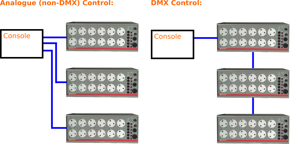
As a result of these disadvantages, an industry standard protocol called Digital Multiplexing 512 (DMX512, or simply DMX) was established in 1986. The main advantage of this protocol was that it allowed for any DMX dimmer packs to be daisy-chained from each other, with only one cable coming from the central console, and up to 512 channels of individual dimming (a dimmer pack such as the one below consists of six dimmed channels) controllable over this cable. This is shown in the below topological diagram, where a blue line indicates a data control cable:

Daisy-chaining dimmer pack controls through DMX proves highly useful in reducing the number of wires needed to carry control signals between backstage dimming gear and a lighting control console. Furthermore, the DMX protocol encodes dimmer data using multiplexed digital signals as opposed to individual analogue ones. Digital technology is, as a rule, less susceptible to data degradation and electromagnetic interference than analogue alternatives.
One must not be misled into thinking that the presence of a certain topological layout necessarily implies the presence of a particular analogue or digital transmission standard. Indeed, there do exist very rare analogue control systems, such as the D54 protocol developed by Strand Electric, which still allow for dimmer packs to be daisy-chained. The defining feature of a daisy chain control topology is that each individual channel of control is not exclusively dependent on a single copper conductor wire; instead, a small number of copper conductors are used to carry dedicated multiplexed data to very many channels.
[Top of Section] [Top of Page] [Theatre Lighting Contents]
DMX transmits control data data using a serial digital (binary-encoded) transmission standard called RS485. This means that a DMX data cable only contains a minimum of three separate copper cores (unlike analogue control cables which require one core per control channel); the data is transmitted over these copper cores by repeatedly sending data for each channel of control in rapid succession. This also means that DMX data cables, discussed subsequently to this, can be thinner and simpler than multi-core analogue control cables in spite of the fact that one DMX cable can actually carry data to a greatly higher number of control channels than a single analogue control cable.
In essence, DMX channels are controlled from the console via the following procedure. The steps assume that each control channel consists of a simple dimmer parameter:
If, for example in a particularly large theatre, more than 512 channels of dimming (DMX's upper limit - also termed one universe) are required, a console may be used which can output DMX data to two or more daisy chains (universes) of DMX devices.
The inherent daisy chain nature of the DMX protocol is such that the 44Hz-refreshed data for every device on the universe is received by every device connected to the universe. However, each device only samples a small section (determined by its identification address(es)) of such data which corresponds to each of its controllable parameters. For example, out of all the 512 addresses of control for a whole universe "moving through" a six-channel dimmer pack, it will only sample a group of six addresses within that range, one for each of its channels. The rest are ignored by that particular dimmer pack. Another six-channel dimmer pack on the same universe, on the other hand, will sample a different set of six addresses from the overall control data stream.
DMX is a particularly useful transmission protocol because it allows for the control, not only of simple dimmer packs, but of more complicated theatrical devices such as those discussed in Hardware 5: Advanced DMX devices.
[Top of Section] [Top of Page] [Theatre Lighting Contents]
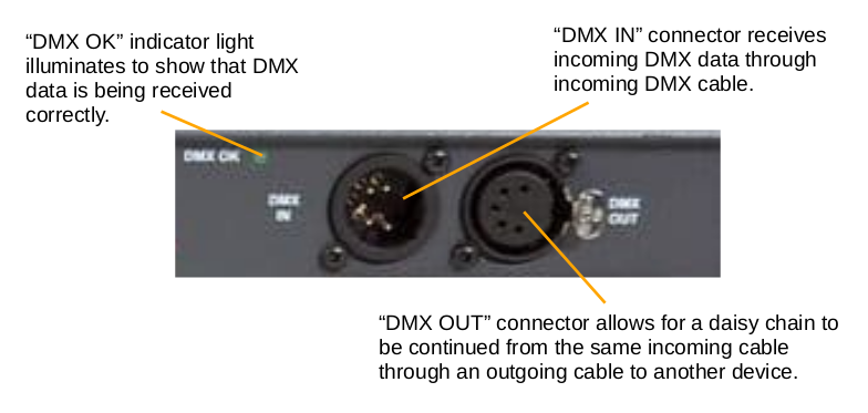
Next, we must explore the exact means of physical connection used for DMX data cables between a console and its controlled lighting equipment. Since DMX allows for devices to be daisy-chained, any DMX-controlled device (with the exception of the master control console, which is always at the start of the daisy chain) will have two DMX data connection points. These are termed "DMX in" and "DMX through". The purpose of the former is to accept an incoming signal from the console and the purpose of the latter is to allow this signal to carry on, through another cable, to the next device in the daisy chain. This is explained in the picture below:

The industry standard connector for DMX devices is a 5-pin XLR connector, of which only three of the pins are generally used. XLR connectors come in a wide variety of pin numbers and also have a variety of applications; they are highly common in audio equipment, especially professional gear. The standard connector used for a DMX input (as shown above left) is a male connector whereas the standard connector used for a DMX output (as shown above right) is a female connector. It important that these standards be adhered to assembling connecting sockets and cables: maintenance of the correct standard will prevent two different DMX data lines from being connected together - an action which would likely result in a short-circuit. A 5-pin XLR cable is shown below:

Following on from the aforementioned aspect of 3-pin XLR connectors being used in audio applications, it is also highly important to note that some non-compliant (according to the original DMX512 standard) DMX devices also use male and female 3-pin XLR connectors as a means of connecting to a source of DMX control data. This is mainly the case owing to the slightly improved durability of 3-pin XLR connectors over their 5-pin counterparts. However, this non-compliant use of 3-pin connectors poses major risks of performance degradation, or even of malfunction.
Performance degradation can arise if 3-pin XLR audio cables (as opposed to dedicated, but non-compliant 3-pin DMX cables) are used to transmit DMX data between DMX devices: audio cables generally have a higher internal capacitance compared with dedicated DMX cables which can create timing problems with the DMX signal since, at 44Hz, any delay or time shift of the signal created by capacitance at any point in the daisy chain can create severe sampling co-ordination issues for the whole daisy chain of devices, thus opening up the potential for unpredictable operation of lights or similar connected devices.
At a minimum level, risks could manifest themselves through irritating confusion between audio cables and DMX cables, since 3-pin XLR cables are very common in professional and high-end consumer audio equipment. In a worst-case scenario, a 3-pin DMX cable could be connected to an audio cable carrying 48v "phantom power" intended to connect to a microphone. Since DMX devices normally use electrical signals no greater than 5v in magnitude, 48v phantom power could severely damage the DMX receiving circuitry not only in the next directly connected device, but in every other device on the daisy chain, since they are all linked over the same cable.
A further and even more extreme risk involves the fact that a number of online manufacturers of poorly constructed smoke machines are adopting the dubious practice of using 3-pin XLR connectors as a means of transmitting mains electricity at 240v to the smoke machine and a proprietary remote switch box. Clearly, XLR connectors are not rated for mains voltages; but these manufacturers generally utilise them owing to their low price and visually robust appearance. However, if a standard XLR cable were connected to a mains-voltage XLR socket of this kind, not only could the metal sheath around each end become live and deliver an electric shock, but any equipment mistakenly connected to the other end of the cable (for example, a lighting console, if it was thought that such a mains-voltage XLR connector was intended for DMX connection) could be severely damaged, even malfunctioning in a potentially explosive and therefore dangerous manner.