Theatre Lighting Intro - Hardware 5
[Theatre Lighting Contents Page]In spite of the fact that the DMX protocol is traditionally orientated around control of stage lighting, there exist many other theatrical devices which may also be controlled over DMX from the central lighting console. It is therefore important to have an understanding of the modes of operation of such devices. This section complements the earlier section, Hardware 2: Introduction to DMX Control.
Many productions often benefit from the presence of haze or smoke for enhanced atmospheric effects. A number of methods for creating theatrical smoke exist. The simplest way to create smoke is to burn combustible items. However, the smoke produced is unpredictable in volume/density and the heat from the combustion poses a major fire hazard.
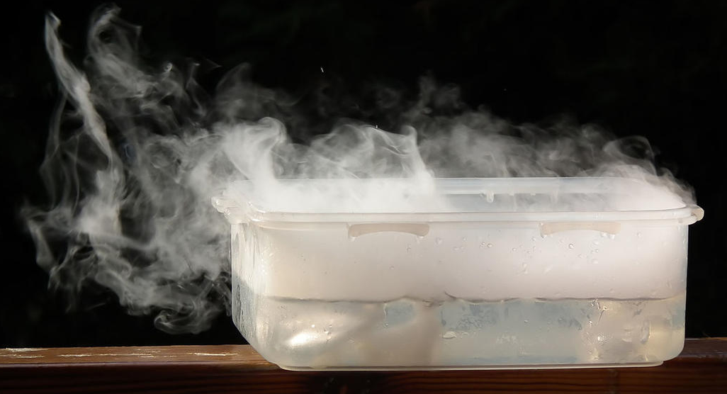
An alternative and cheap method of creating smoke effects with significantly improved safety compared with simple combustion is by the sublimation of carbon dioxide. Carbon dioxide is quite a rare substance in that it changes directly from a solid phase (below -78.5 degrees Celsius) to a gas phase (above -78.5 degrees Celsius) with no intermediate liquid state. This process of sublimation means that if a solid block of carbon dioxide (popularly known as "dry ice") is melted by placing it in water at room temperature, a large quantity of thick foggy smoke is produced. As a bonus, this smoke does not cause eye or respiratory irritation. By altering the volume of dry ice allowed into the water per second, it is possible to adjust the density of the smoke produced to a desired level. Below is shown the smoke produced from the sublimation of dry ice upon immersion in water:
In practice, however, dry ice is somewhat impractical as a source of theatrical smoke not only because the solid dry ice will tend to melt when stored before use, but also owing to the fact that a dry ice smoke vessel cannot be controlled remotely as is desirable in a theatre: an operator must manually move the lumps of dry ice into the water as and when smoke is required. Furthermore, the smoke produced is tricky to direct outwards across a stage, often requiring external fans to accomplish this.
In light of these factors, one of the most common techniques for producing theatrical smoke is through the vaporisation of glycerol. This results in a similar smoke or haze which does not irritate one's eyes or airways. In addition, glycerol can be used to produce smoke from its liquid form, thus allowing for easier long term storage without the need for refrigeration.
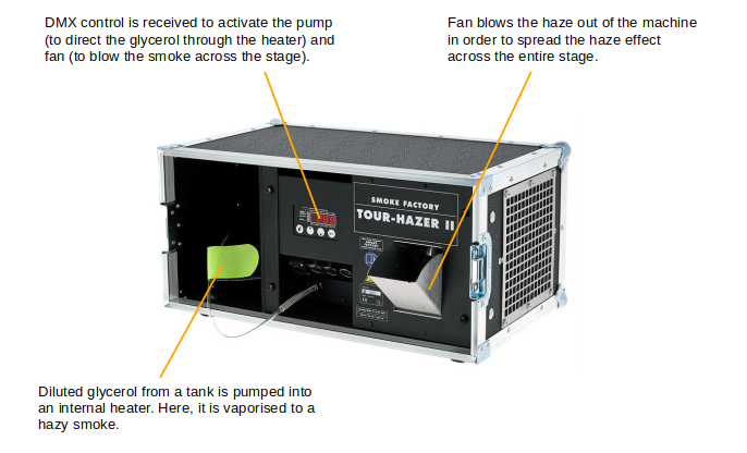
Glycerol smoke machines contain a tank of glycerol fluid. This is pumped electrically through a heating chamber where it is vaporised to "smoke" which exits through the front of the machine. Some such machines - especially those intended to create overall "haze" as opposed to dense smoke - contain an electric fan in order to blow the smoke produced across the stage. This means that the machine itself can be placed in a wing space behind or beside the stage such that it is out of sight and still produces the required smoke.
Since the internal operation of a glycerol smoke machine is entirely electrical, it is easy to remotely operate the machine. This is accomplished over DMX; the pump and fan are addressed separately - each receives its own dedicated DMX control channel - such that the speed of each can be adjusted by a standard 0-255 binary-encoded multiplexed DMX signal. DMX smoke machines can be connected to an existing daisy chain of devices such as dimmer packs and/or intelligent fixtures.
Below is shown a glycerol haze machine (Smoke Factory Tour Hazer):
[Top of Section] [Top of Page] [Theatre Lighting Contents]
An electrical relay switch is a very versatile device. It consists of a normal switch such as that used to operate simple room lights but with an important difference: the on/off action of the switch is actuated by remotely sending the relay switch an independent pulse of electric current. When the device receives this independent electric current, an electromagnet engages the two main switched contacts, thus completing the circuit through these primary contacts. When secondary power is removed from the relay, the electromagnet loses its magnetism and the switched terminals disengage.
This characteristic of relays renders them ideal for switching high-power electrical circuits from a separate low-power source: the current applied to the actuating coil may be very low, whereas the current through the switched terminals may be significantly higher.
One may recall from H3.4 - Phase Angle Semiconductor Lamp Dimmers, that a transistor is similar to a relay in that it regulates the flow of current through its two primary contacts based on a lower-current secondary input. However, semiconductors are very limited in their ability to switch high-power electrical loads. A triac - the vital semiconductor component in a phase angle light dimmer - represents essentially the upper limit of semiconductors in switching such loads. Electromechanical relay switches are excellent for switching high-power electrical devices between on and off states but, unlike a transistor, they are incapable of varying the current flow through their primary connections other than between an on state or an off state.
Below: an internal schematic of a relay switch. The solenoid coil is energised and therefore magnetised by the independent low-power side such that the switch for the high-power side may be magnetically operated by this remote low-current pulse of power:
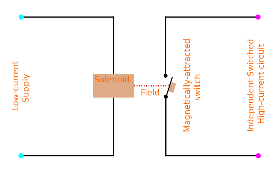
This diagram clearly highlights the fact that the low-current trigger circuit (that connected to the coil) is totally electrically isolated from the high-current side (that which is switched): the low-current circuit is an independent connection for the control of the switching of the high-current circuit. The coupling between the low-current control side and the high-current switched side is provided by the magnetic field established around the solenoid when it receives power. This field actuates the high-power switch.
Remote relay switches are useful in theatrical productions for switching electrical devices which cannot be connected to dimmer packs (excluding intelligent or LED lighting fixtures, which have internal DMX receivers and control gear). They allow for the switching of so-called "practicals" - physical lights which are part of the set such as a street lamp (on stage as part of a backdrop, for example) whose gas discharge mode of operation would render it unsuitable for receiving dimmed power. Similarly, sometimes it is desirable to use fans, positioned in the wings such that they bring about airflow on stage, to create controlled illusions of wind. Electric motors must also receive a source of switched, constant power and are therefore often controlled by such relays.
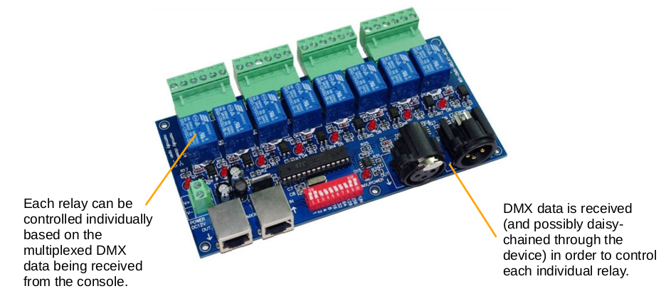
A typical remote-control relay for theatrical use receives a DMX input from the central lighting desk. Again, this DMX input may be daisy-chained to an entire universe of DMX devices likely already installed for console control. An internal DMX decoder receives a control signal from the console and uses this to activate the electromechanical relay, thus energising the connected device at the correct points in a show.
Below is a DMX relay module. It is common for theatrical devices such as these to be shipped as a standalone printed circuit board (PCB) for improved versatility when installing in a theatrical setting. This particular board has eight individually controllable relay switches (blue surface-mounted boxes):
[Top of Section] [Top of Page] [Theatre Lighting Contents]
A pyrotechnic device refers to a machine which produces some kind of visible flame for use in a production. These are different to smoke machines in that the main reason for their use is not to produce smoke - in many cases, pyrotechnic machines use clean-burning fuels such as propane in order not to create undesirable indoor pollution - but to create large, vivid, yellow flames.
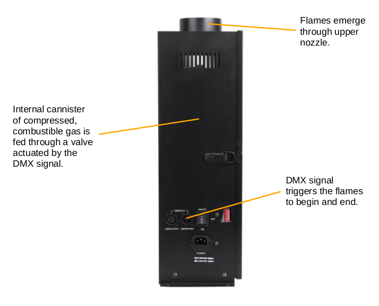
The inner workings of a pyrotechnic device are quite simple. An electronically controlled valve, opened and closed based on a DMX control signal, regulates the flow of butane/propane gas out of a pressurised cannister such as that used in a portable camping stove. When the signal is received for the valve to open, the propane/butane is allowed to emerge from the cannister. Now it is necessary to have some means of igniting the gas upon its first emerging from the cannister, otherwise it would fill the venue with dangerously inflammable vapour. This means of ignition is provided by a simple spark such as a spark plug from an internal combustion engine. This is triggered briefly, as soon as the valve opens, to initiate the combustion.
The output flame can be triggered and pulsed from the central console. Once again, the pyrotechnic device may be daisy-chained via DMX cabling in conjunction with other apparatus such as dimmer packs and intelligent fixtures.
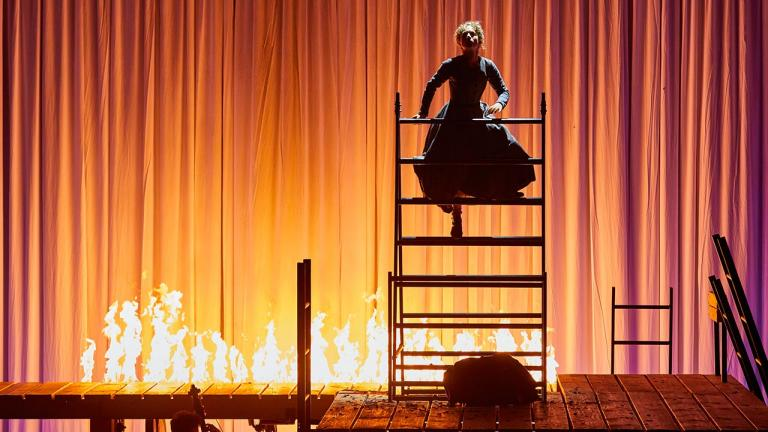
Below is shown a set of theatrical pyrotechnic devices (flame throwers) in operation for the National Theatre's 2017 production of Jane Eyre:
Below: a DMX flame thrower device:
It is important to note that some pyrotechnic devices may not operate exclusively from a DMX control signal; they may require a secondary confirmatory trigger signal in order to avoid potentially unsafe false triggering. This secondary trigger is generally made by directly interrupting the internal electrical supply cable to the electronic valve on the gas cannister's output independently to the DMX trigger control. This wiring is then brought out to a secondary switch which may be operated by a "dead man's handle" located at the side of the stage - a device which only completes the circuit to the electronic valve once a second operator is continuously depressing two discrete buttons. Once this second operator is in place and pushing down the two buttons, the device may respond to the control signal emanating from the main control console. If the second operator notices a potentially unsafe situation, they can immediately remove one or both hands from the dead man's handle device and the pyrotechnic device will cease to function. Furthermore, since continuous pressure is required on both the buttons of the dead man's handle (typically one button for each hand of the second operator) for the circuit to be completed, the second operator cannot become distracted/fall asleep from monitoring the device and surrounding area of stage for dangers.
Concerning positioning of pyrotechnic devices, they are generally placed beneath small openings in the stage floor. Unlike smoke machines, they cannot be mounted above the stage on the fly floor such that the flame shoots downwards owing to the fact that flames will tend to move upwards via convection.
[Top of Section] [Top of Page] [Theatre Lighting Contents]
We have seen in H4.7 that the colour of light output from a theatre light may be altered by placing a coloured filter in front of the output. However, on conventional fixtures, this colour filter ("gel") can only be changed by climbing up to the lighting bars using a ladder, cherry picker, or scaffolding tower during the rigging process before a show may run. It is clearly highly impractical to attempt to manually change gels in this manner during a show.
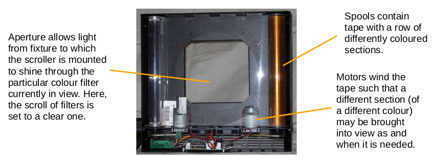
In light of this problem, colour scrollers are sometimes used in theatrical productions to automatically change the colour of light emerging from an incandescent fixture. These are remotely operated from the main console. The layout of a colour scroller can be considered very similar to that of a cassette tape but with a very wide tape composed of gel material consisting of a row of consecutive differently coloured square light filters. This tape is wound onto two spools separated at such a distance that, at any time, only one coloured square on the tape may be made visible between these two spools. It is therefore the case that, by winding the tape backwards and forwards using the spools, different squares of colour can come into view. If this device is mounted onto the front of a light fixture, the light emerging from the fixture is filtered to a particular colour by the particular gel square presently in view on the scroller.
Electric motors are used to wind the scroll of consecutive colour filters backwards and forwards between the two spools in order that one light fixture may be used to produce a variety of different colours. Similar to intelligent or LED fixtures, scrollers require a source of constant electrical power and receive a dedicated DMX data connection such that the winding action of the spool motors may be controlled remotely.
Below is shown a photograph of a partially disassembled colour scroller. The two motors (visible as small silver cylinders, bottom left and bottom right) wind the spools in different directions such that any one of the filter squares present on the moveable filter film may be brought into view in front of the fixture, thus changing the emerging colour of light:
Colour scrollers lack the ability for so-called "live changes" to the colour of a light source. This means that the light fixture must be turned off before the scroller may be wound to a differently coloured section of tape since the winding process moves the boundary(ies) between multiple colour squares across the main aperture in order to reach the desired colour on the tape. If this winding were done with a full level of power applied to the light fixture, a highly visible "sweeping" of colours would be noticeable in the emerging light as the correct section of tape came into view - a generally undesirable characteristic.
[Top of Section] [Top of Page] [Theatre Lighting Contents]
Ordinarily, a DMX universe consists of a linear topology of devices. This means all the controlled devices, be they dimmer packs or intelligent/LED fixtures, connect to each other in one simple daisy chain. However, there may be times when it becomes inconvenient to have DMX devices connected in such a manner. For example, it may be preferable, in order to minimise the transmission cable length, to split the cable in two very different directions, each heading to a completely different section of the venue. Since DMX data is multiplexed along the cable, every device would still receive individual control.
One may think that the aforementioned splitting of a cable may be achieved purely physically by splicing together two DMX data cables in a "Y" fashion such that the incoming data from the console splits into two branches, each heading to different parts of the venue (for example, one may head to the backstage dimer packs, whereas another may head to any intelligent fixtures on the lighting bars which require dedicated control). However, such a method of splitting DMX data frequently produces unreliable operation. This is owing to the fact that every time a split is made in the wire, the strength of the DMX data signal encoded on the wire decreases significantly. Therefore, this method is obviously unreliable if used in excess since it may cause the signal to fade to complete undetectability, thus rendering any attempted signalling useless.
As a result of the above problems, if a DMX data line must be split, a DMX buffer is used. This not only splits the incoming signal to many more "branches", but also amplifies the magnitude of the signal such that each "branch" still receives a signal of an adequate strength. DMX buffers typically input and output the data over the industry standard 5-pin XLR connectors such that any devices/cables may be connected.
Below is shown a basic DMX buffer. The incoming data is amplified and split to each of four sockets in order to eliminate the chance of undetectability. The cable emerging from each socket may be looped through sets of devices as usual. A DC input is also necessary in order to provide the additional signal amplification power:

DMX buffers also find use if unusually long runs of DMX cable need to be made (for example, between two buildings): one can place buffers at several points along such a long line in order to maintain the strength of the signal over such a distance where normally even the electrical resistance of the wire itself could cause signal degradation.
NOTE: In spite of the fact that DMX buffers produce outputs to a set of multiple ports, each of which may be daisy-chained to a number of devices, they do not increase the number of universes present: the maximum total number of possible addresses remains at 512 as usual.