Theatre Lighting Intro - Hardware 3
[Theatre Lighting Contents Page]Lighting dimmers and their corresponding stage lights form the backbone of nearly all theatres. It is therefore important to have a firm understanding of the technologies used to achieve dimming effects. This chapter is complemented by the previous one, Hardware 2: Introduction to DMX Control for the simple reason that the DMX protocol is used to control many modern lighting dimmers in a convenient and flexible manner which is not possible with older, purely analogue, control methods.
The exact dimming circuitry described in the subsequent chapters of this section is orientated around analogue means of control for the sake of clarity of explanation. DMX-to-analogue conversion, as is now standard in any DMX-controllable dimmer pack, is discussed after that.
In any theatrical or stage-orientated lighting scenario, it is desirable that the lights have the potential to be dimmed. This can alter the created "mood" but also allows for the lights to be faded up or down to create smooth transitions between different lighting scenes as opposed to the sudden changes offered by simply switching certain lights on and off.
Theatre and similar professional environments are not the only applications where dimming may be desirable: many manufacturers of simple wall-mounted light switches for use in homes also produce wall-plate "dimmer switches" which allow for the intensity of the light bulb illuminating a particular room to be reduced from its full intensity to anywhere between that and zero.
Below: a common domestic rotary dimmer switch:
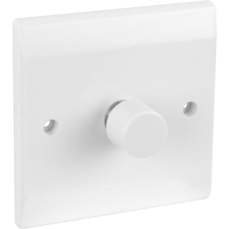
Such domestic dimmer switches are now becoming rarer owing to their general inability to correctly control modern low-energy light bulbs when such bulbs are used in place of the intended incandescent lamps. For theatrical purposes, however, incandescent lights are still commonplace owing to the fact that, unlike for use in the home, incandescent lights have not been banned for theatrical use by the European Union. For more information on theatrical lighting technology and fixtures see Hardware 4: Theatre Stage Lights.
[Top of Section] [Top of Page] [Theatre Lighting Contents]
The simplest way of dimming an incandescent light bulb is by placing it in series with a variable resistor, or rheostat. This means that, depending upon how the wiper of the variable resistor is adjusted, a large portion of the input power will be dissipated either by the resistor (with the bulb at a low intensity) or by the bulb itself (with the bulb at a high intensity). This arrangement follows that of a simple resistive voltage divider, with the supply voltage being split between the bulb and the variable resistor depending on their proportional resistances. A schematic diagram of this arrangement is shown below:
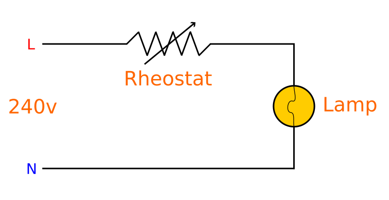
The main problem with this resistive method of dimming a light is the inherent inefficiency of such a system: when the lamp is at a low intensity, one would assume that, in such a state, the circuit should be drawing a minimal amount of current. In fact, with this arrangement, such is not the case owing to the fact that, with the bulb at a low intensity, the overall current draw remains identical to what it would be with the bulb at a high intensity, with the rheostat simply "burning off" the excess energy (that not being used to illuminate the bulb) as heat, leaving a lower proportion of the power available to the bulb with the result that the bulb is dimmer. When being used with high-power electrical supplies for similarly powerful lights, this excess heat creates a fire hazard if many such dimmers are being used.
Another problem with this arrangement is the inability for it to be controlled at a distance: in a theatrical establishment, it is customary to control the large high-voltage dimmers at a distance from a relatively small console which operates only with safely low voltages. However, with a resistive dimming arrangement, this is impossible and every high-power rheostat for each dimmed light must be located in place of the console, thus creating the need for heavy high-current wires to be run between these and each dimmed light for which control is required. Furthermore, high-current rheostats are very large devices compared with the small "sliders" found on modern lighting consoles, thus meaning that if a great many lights are to be controlled, the rheostat-based "console" may become impractically large.
An ideal dimming arrangement should consist of the large high-voltage dimming equipment located backstage (also most likely the point where the high-power electrical utility service enters the building, thus eliminating the need for bulky high-power cables to be run to the console location) with a small, low-voltage-operated console in the auditorium for safe and easy operation at a point from which one can see the stage. The console then sends low-voltage control signals to the backstage dimming equipment in order to adjust the intensity of desired dimmed channels.
[Top of Section] [Top of Page] [Theatre Lighting Contents]
To address the inefficiency of resistive dimmers, an improved dimming system was later developed using variable autotransformers. An autotransformer is very similar to a standard electrical transformer for efficiently stepping up or stepping down alternating currents except that, unlike standard transformers, which consist of discrete primary and secondary windings, an autotransformer consists solely of one winding - portions of which act as both a primary coil and a secondary coil simultaneously. This winding is wrapped round an iron core as is the case with a standard transformer. The voltage obtained from an autotransformer can be adjusted by tapping off from the coil on the "secondary level" at different points.
A schematic diagram of a variable autotransformer is shown below. This very clearly illustrates the way in which a single coil acts as both the primary and secondary windings of a conventional transformer. The primary side spans a fixed portion of the coil whereas the exact position at which the secondary side "taps off" is variable. Multiple grey "tap-off" points serve to alter the magnitude of the secondary voltage:
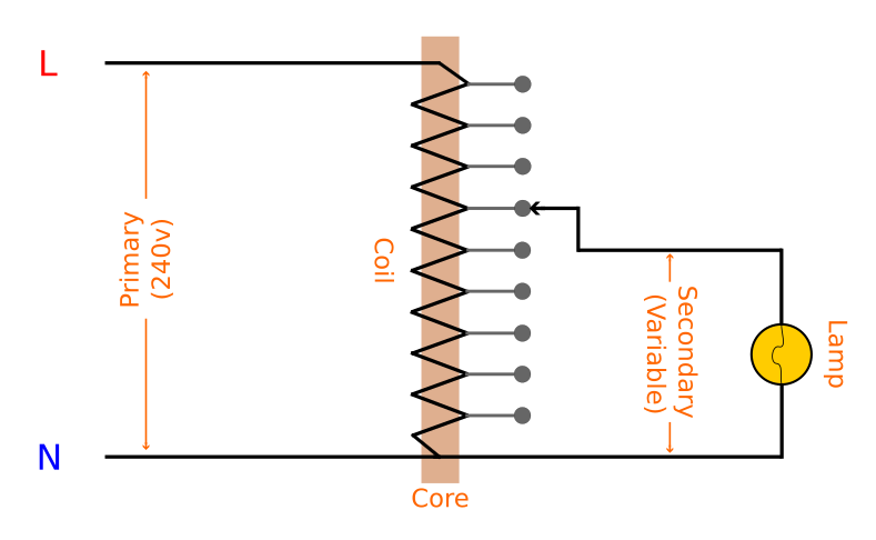
The ratio input voltage:output voltage may be calculated in exactly the same way as with a standard transformer, using the ratio of the numbers of "turns" allocated to the primary and secondary levels based on the position of the tap-off point:

Where Vp and Vs refer to the voltages on the primary and secondary sides respectively, and Np and Ns refer to the number of turns on the primary and secondary coils respectively. Altering the tap-off point on the secondary side has the effect of changing the number of "turns" on the secondary level, thus altering the output voltage and adjusting the lamp's intensity.
In the above diagram, only a finite number of tap-off points are shown. However, by using a wiper contact for the secondary side, similar to that of a rheostat, to adjust the portion of the coil being energised, an infinitely variable output voltage may be obtained. This state of affairs is also termed a "Variac" - the name of the company which originally developed such variable autotransformers.
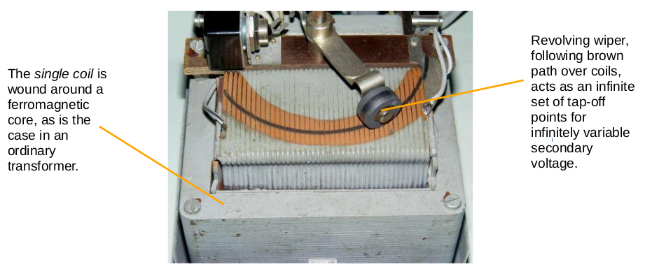
Unlike a rheostat, an autotransformer can be used to reduce the voltage applied to a light without the unnecessary dissipation of heat. The main difference which causes this is that the rheostat does not alter the supply voltage - simply what portion of that constant voltage's power it wastes as heat in order to dim the light, whereas a variable autotransformer genuinely alters the incoming supply voltage such that the current through the lamp may be reduced as a result, thus truly reducing the circuit's power consumption with the result that no wasted heat is produced.
Although an improvement over simple resistive dimming technologies, variable autotransformers still lack the ability to be adjusted easily from a distance (one will recall from earlier that a desirable theatrical lighting arrangement consists of a separate control unit and dimmer array) since they still ultimately rely on the mechanical movement of a wiper over coils - the same motion as that of a rheostat. Of course, it is possible to provide a mechanical linkage between a console and Variac wipers over a distance by using gears or similar purely mechanical transmission methods to transmit a turning motion from the console to a backstage Variac but this will still add unnecessary complication to the required arrangement and may still result in a number of unwieldy mechanical control linkages. As such, since a superior means of dimming lights was still desired, semiconductor-based dimming technologies were introduced to address the aforementioned issues.
[Top of Section] [Top of Page] [Theatre Lighting Contents]
A semiconductor is an electrical component which exhibits the characteristics of both an insulator against electric current and also of a conductor of electricity depending on the nature of its electrical input. For example, an elementary semiconductor component, the transistor, can conduct a proportionally large DC electric current through its primary electrical connectors (the "emitter" and "collector") when a comparatively small DC electric current is applied to its secondary "base" terminal:
Below: a circuit schematic symbol for a transistor:

The mode of operation of a transistor can be considered to be greatly similar to that of a valve in a water pipe. The minimal turning of the valve (applying a small electric current to the third terminal) allows for a large flow of water through the pipes and valve (the primary two terminals).
Semiconductors are more robust than mechanical voltage control methods owing to their total lack of moving parts. They also have very rapid response times for applications which require the rapid switching of current (a synoptic example of this could be seen in the creation of digital DMX signals which require the encoding of 512 control data channels 44 times per second, as discussed in H2.2 - Principles of Operation of DMX Transmission).
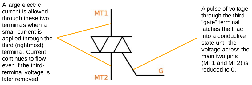
The particular component used in lighting dimmers is a triac. This can be considered similar to a transistor except with an important difference: it only requires a small pulse of voltage to its secondary (gate) input and will latch the primary connectors into a conductive state such that they will conduct even if the gate input voltage is subsequently removed. After this, the only way to make it unlatch is by removing the voltage across the two primary pins (not the third gate pin). This binary "latching transistor" action makes triacs ideal for modulating alternating current, as discussed later in this section. Triacs, unlike transistors, are also capable of switching current flowing in either direction, thus further optimising them for switching bi-directional AC power.
Below: a circuit schematic symbol for a triac:
Another noteworthy aspect regarding triacs is that, somewhat unusually for semiconductors, they are designed to handle high-power electrical loads. This is important if they are to be used to control high-intensity incandescent stage lights.
The following schematic shows a basic circuit, such as that employed in domestic dimmer switches, which utilises a triac to adjust the intensity of an incandescent lamp:
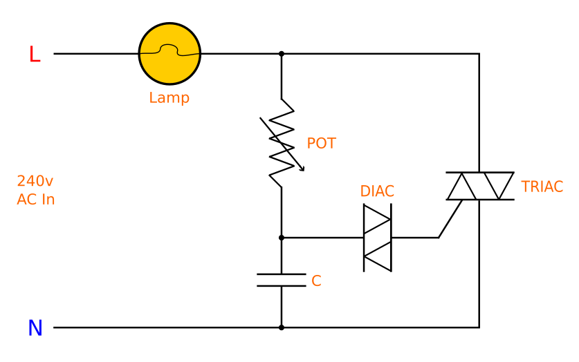
The circuit contains the following components:
An easy way in which one can remember the difference between the diac and the triac, in spite of their almost identical circuit symbols, is through the fact that the diac only has two electrical connections whereas the triac has three electrical connections.
It is important to note the fact that triac-based dimming circuitry only works correctly with an alternating current input. This is because the nature of the mains sine-wave, with its repeated zero crossing points of the horizontal axis (see H1.1 - Mains Electricity Theory of Operation) provides the triac with the requisite momentary lack of voltage across its main two pins which, as discussed above, is the only way in which it can "unlatch".
The operation of a triac lamp dimmer circuit can be summarised in the following stages:
The modified 50Hz waveform produced by such a circuit is shown below:

One may wonder why this extremely choppy waveform does not result in a visible flickering of the light. The answer to this is through the fact that this process happens twice in one full wave (100Hz) in conjunction with the fact that the high thermal inertia of the lamp's incandescent filament "irons out" the pulses of voltage to give a constant, lower-intensity, average light output.
In a theatrical context, this is a highly convenient method of dimming not only because it is efficient and reliable, but because the potentiometer, POT, for each dimmer circuit can be located far away from the backstage dimmer circuits in a compact console with only a thin low-current control wire leading backstage for each dimmed channel of control. In a simple analogue (not DMX-based) lighting console, each slider effectively acts directly as the POT for a backstage triac dimmer circuit.
[Top of Section] [Top of Page] [Theatre Lighting Contents]
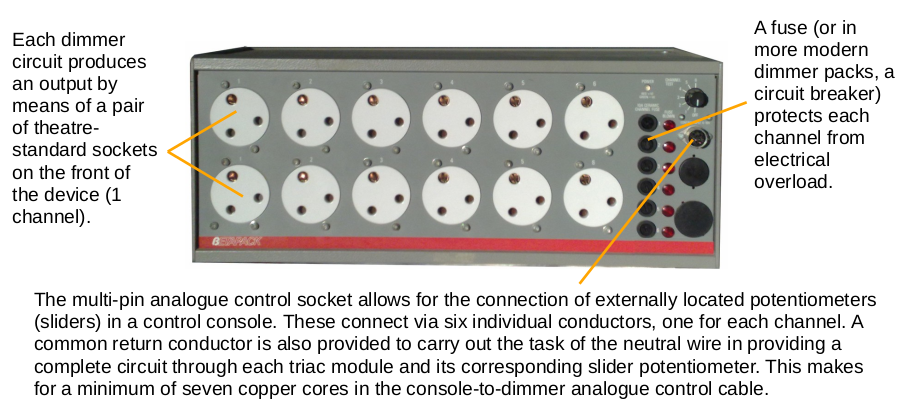
Of course, the aforementioned dimmer circuit only produces one dimmed output. However, theatrical environments will require many more channels of controlled dimming. This is where so-called "dimmer packs" are used. A dimmer pack is, in essence, a backstage-located device which contains a large number (generally six) of triac dimming circuits similar to those in the previous section. An external connector is provided such that each circuit's potentiometer - the component which varies the degree of dimming - may be connected remotely from the dimmer itself by means of a distantly located lighting console's slider (for analogue control only - see below for DMX explanation). Sockets on the front of the unit allow for easy connection to stage lights. A high-current electrical input to the unit is achieved either by hard-wiring it into a building's electrical wiring, or by a 32A/63A CEEform connector. The dimmed output sockets from such a dimmer pack are generally provided by means of theatre-standard 15A round-pin sockets, although other connectors such as miniature (16A) CEEform sockets and Powercon connectors are also found on some modern dimmer packs.
Below: a Zero88 Betapack dimmer pack:
One will recall from Hardware 2: Introduction to DMX Control, that most modern theatrical equipment now communicates over the DMX protocol. This includes dimmer packs. One will also recall that DMX allows for dimmer packs to be daisy-chained and controlled over fewer cables than if each channel were directly connected to its own triac control potentiometer.
DMX dimmer packs are not controlled via a multi-core direct analogue electrical connection to the console. Instead, the digital control data sent by the console enters the dimmer pack through DMX XLR connectors and is decoded (based on its range of channel identification addresses: each channel of the multiplexed signal has its own identifier) inside the dimmer pack itself by circuitry which then produces the requisite potentiometer-style variable-voltage control output within the dimmer pack to operate the triac circuits. A "DMX Through" socket is always provided to allow for convenient daisy-chaining. A DMX dimmer pack is generally significantly more expensive than a simple direct-control analogue alternative owing to the comparatively complex digital-to-analogue conversion circuitry used to decode sections of the incoming digital signal to an analogue format which can control each channel's triac circuit.
In terms of their operation, it is the case that all dimmer packs are analogue with regards to their internal dimming action (a dimmed light is, after all, a continuous analogue output; certainly not a binary digital one). The presence of digital DMX capability does not mean that a dimmer pack is not analogue in terms of its dimming circuitry; instead, that it contains an internal DMX-to-analogue converter.
Below: a DMX-based Zero88 Betapack 3 dimmer pack. Note the total absence of an analogue potentiometer-orientated DIN connector:
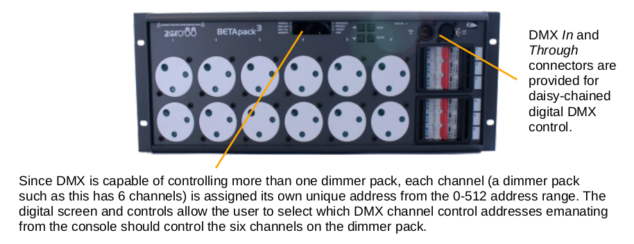
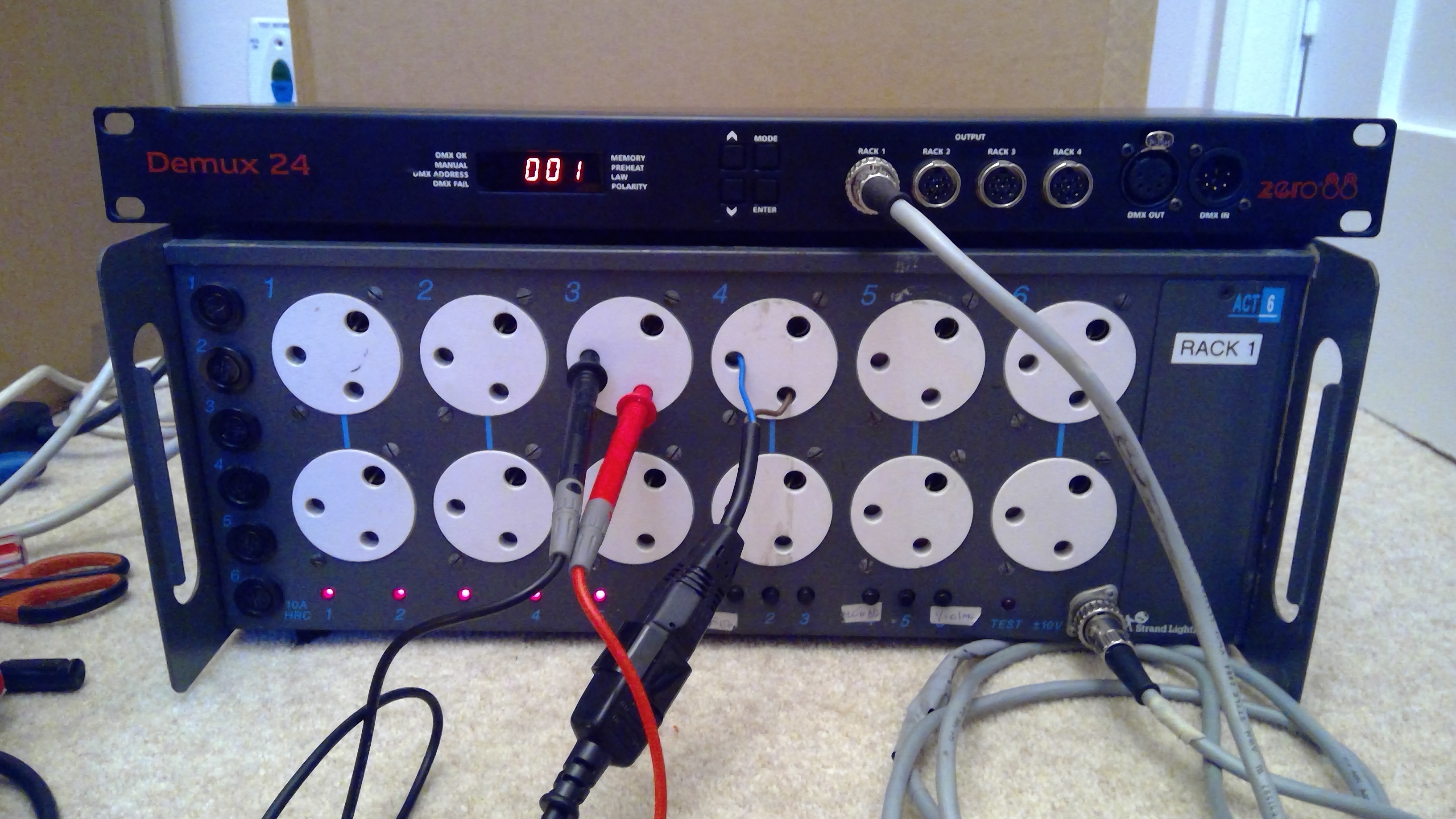
Fairly obviously, if a theatre desires to transition its lighting console from an analogue to a DMX-based type, it can prove highly expensive to replace existing functional simple analogue dimmer packs with DMX-capable models such as the one above. This is where a demultimplexer (or "demux") becomes of use. This is a device which receives a multiplexed DMX input from the control console and converts this into one or more legacy multi-pin analogue control outputs which can then be connected to traditional dimmer packs with no onboard provision for DMX decoding.
Below: a demultiplexer (Zero88 Demux24):

Below: a demultiplexer of the above kind connected to an analogue dimmer pack (Strand Act 6+). The wires inserted into the dimmer pack sockets are to test the output voltage. No DMX input to the demultiplexer is shown:
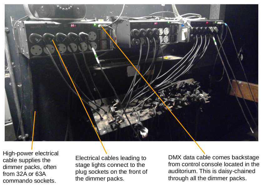
Below: a typical arrangement of backstage dimmer packs (Zero88 Betapack 3s):
[Top of Section] [Top of Page] [Theatre Lighting Contents]
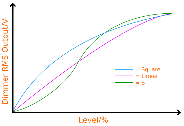
The law of a dimmer refers to the way in which the rate of change of intensity of its light varies with the level of the control input signal, for example the movement of the potentiometer in the circuit shown in H3.4 - Phase Angle Semiconductor Lamp Dimmers.
In a standard mode of operation, a lamp dimmer has a non-linear response. This means that, in the case of a 0-255 DMX signal for one channel of dimming being sent from a console to a dimmer, although 0 corresponds to off and 255 to full intensity, the transitional intensity of the lamp is not exactly proportional to the actual numerical value on the DMX address of control. For example, if the console slider corresponding to such a light were slowly moved at a constant rate from 0% (address control signal: 0) to 100% (address control signal: 255), the intensity of the light would increase slowly towards the bottom and top of the slider's travel and quickly during the centre of its range. If the dimmer's response were plotted on a graph with DMX control input horizontally and light intensity vertically, the line would have a flatter gradient towards the origin and towards its upper end, and a steeper gradient at its centre. This line is referred to as an "S" curve owing to its shape.
This oddity can be explained by considering the mode of operation of triac dimmers. As discussed in H3.4 - Phase Angle Semiconductor Lamp Dimmers, a triac dimmer circuit truncates portions of each half-wave from the mains sine-wave in order to reduce the area of each half-wave and the resultant RMS voltage delivered to the lamp - RMS voltage depends on the integral of the wave (i.e. its area). Now at very low percentage levels, only a small portion of the half-wave may be left over from the triac cut-on point (see illustration of triac switching action in H3.4 - Phase Angle Semiconductor Lamp Dimmers). Since a very small end portion of the half-wave remains, the area between such a portion and the horizontal axis is low (see triac circuit output waveforms shown in H3.4 - Phase Angle Semiconductor Lamp Dimmers). This means that, if the dimmer slider is increased by a very small degree at a very low level, the corresponding increase in area brought about by the triac and its now-altered cut-on point is still low and the increase in light intensity is similarly low. However, if the slider is moved by the same small degree within the centre of its range, the triac is now adding area to the centre of the half-wave. Since the half-waves of the mains sine-wave are arch shaped, this means that any small movement in the cut-on point of the triac here brings about a large increase in area - that within the middle of the "arch" - compared with what would be achieved at each end of the arch-shaped half-wave. Larger increases in area for each degree of slider movement mean that the rate of change of light intensity is greater towards the centre of the slider's range.
This infinitesimal relationship between a small slider movement and the corresponding change in triac-modulated area of the half-wave may also be expressed using calculus, by taking derivatives from a graph of half-wave area (as modulated by the triac) against slider position (DMX signal). This procedure will result in a confirmation of the aforementioned "S" shaped, or "S-law" dimming curve. All triac-based dimmers produce an S-law output by default. For most environments which utilise triac dimmers, such as domestic dimmer switches for room lights, an S-law output is perfectly adequate.
However, S-law dimming does not allow for the particularly precise control of lamp brightness in the middle range: a small slider movement in the middle region of travel results in a significant change in brightness. This may be undesirable for theatrical or televisual applications where a linear (or possibly even more different) response would be ideal. As a result, sophisticated dimmer packs may allow for the dimmer law to be altered between multiple different preset types. The dimmer pack then creates a small "fudge factor" on the incoming control signals such that the internal triacs respond to these signals in such a way as to bring about a more linear dimming response.
Dimmer laws are typically adjusted on multi-law dimmer packs themselves using integrated switches, miniature potentiometers, or digital controls. Sophisticated consoles also have the ability to alter the dimming law by directly introducing the aforementioned "fudge factor" directly onto their output DMX data. However, this method of adjusting the law via the console may prove less accurate than adjusting the law on the dimmer itself. This is because it is impossible to optimise the console's creation of the "fudge factor" for every subtly different triac dimming circuit.
The three most common types of dimmer law are as follows:
A graphical representation of the three main types of dimmer law is shown below through a graph of output dimmer voltage (light intensity) against DMX percentage level. Whereas the dimming response is highly variable for a basic S-law, it is largely linearised for a linear law, and further altered for a square law in order that the upper level region may offer finer dimming control:
