Theatre Lighting Intro: Hardware 1
[Theatre Lighting Contents Page]In order to fully understand theatre technology, especially that which is used for lighting, it is very important to have a firm grasp of more general electrical systems and their principles of operation since these are closely intertwined with those of lighting devices.
Most buildings in Britain receive a mains electricity supply of 240v AC at 50Hz (50 cycles per second). This means that the current entering the building changes direction 50 times per second between positive and negative directions of flow. If one plots a graph of how voltage fluctuates over time for alternating current, it will look like this:
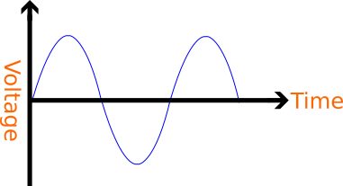
This graph is called a sine-wave and is thus known owing to the fact that it is a plot of the fundamental function y=sin(x), where sin is the trigonometric ratio sine. In the above plot, the top section represents positive voltage (current in one direction) and the bottom section represents negative voltage (current in the other direction).
Current is transmitted in this manner because it is more efficient to transmit electricity over long distances (such as from a power station in an isolated area to a city) using alternating current than using its counterpart: direct current - that which flows in one direction only.
Another highly important fact, especially when considering theatres, is that larger buildings which, unlike domestic properties, are likely to draw large amounts of current for stage lighting and similarly large apparatus receive a three-phase electricity supply along three separate live wires instead of one live wire as would be the case above:
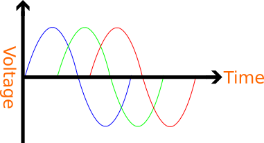
One will notice that this graph of a three-phase supply is three of the above sine-waves but each one shifted a little to the right - 120o, or 2.09 radians - along the horizontal axis from the previous one. For high-current applications (such as large buildings and appliances) it proves to be more economical to transmit electricity as three phases, as opposed to the simple single-phase (above) power since this allows for significantly more electrical power to be delivered to a building over thinner wires than would be required for the same amount of power over a single-phase supply.
If a voltage measurement is taken between any single phase of a three-phase supply and a 0v reference (neutral or ground; see H1.2 - Introduction to Mains Electricity Hardware), this individual phase-to-neutral voltage is 240v as is the case with a standard mains supply. However, if a voltage measurement is taken between two phases, such a phase-to-phase voltage reading will be seen to be 415v. This phenomenon can be explained, to a degree, by observing the three-phase graph shown on the previous page: the vertical difference between two phases, at any point in time where one such phase is at its maximum, is higher than the voltage between only a single phase and the 0v neutral reference (the horizontal axis) at the same instant.
Most of the time, upon entering a building, a three-phase supply will be split up into its three constituent phases, with each phase driving a single-phase 240v electrical load.
One will recall from above that single-phase mains voltage takes the form of a sine-wave at 240v. At this point, it is crucial to understand exactly how the 240v voltage value for mains voltage is obtained owing to the fact that a continuously fluctuating voltage does not ever maintain one single value, as shown in the graphs above. This means that some kind of mean or average must be taken in order to obtain a useful numerical value.
Two common misconceptions regarding the calculation of effective voltage delivered by an AC waveform are as follows:
As a result of the two problems highlighted by these two misconceptions, especially that in part 2, it is evident that a procedure must be used which accounts for the negative voltages by retaining their magnitude without the aforementioned "cancel[ling] out" effect whilst also providing an indicative average value for the voltage.
To calculate the average voltage of a continuous mains-voltage sine-wave, a mathematical technique knows as Root-Mean-Square (RMS) is employed. The effectiveness of this method in eliminating the problem of the "cancelled out" sample values is reliant on the fact that the product of two negative numbers (or, indeed, the square of a single negative number) is always a positive number identical to that which is obtained by simply multiplying the two corresponding positive numbers together. By eliminating the negative sample values in this way, a mean can then be calculated.
The exact procedure used for an RMS voltage calculation is as follows:
This method of RMS calculation is one of the simplest and is reliant on a high number of "sample points" across a full wave in order to achieve a representative reading. The more samples are taken, the more accurate will be the calculated RMS voltage.
The abbreviation RMS is somewhat misleading owing to the fact that the actual necessary sequence of operations consists not of "Root-Mean-Square" but "Square-Mean-Root".
A succinct graphical representation of the sampled RMS voltage method is shown below, complete with the corresponding formula:
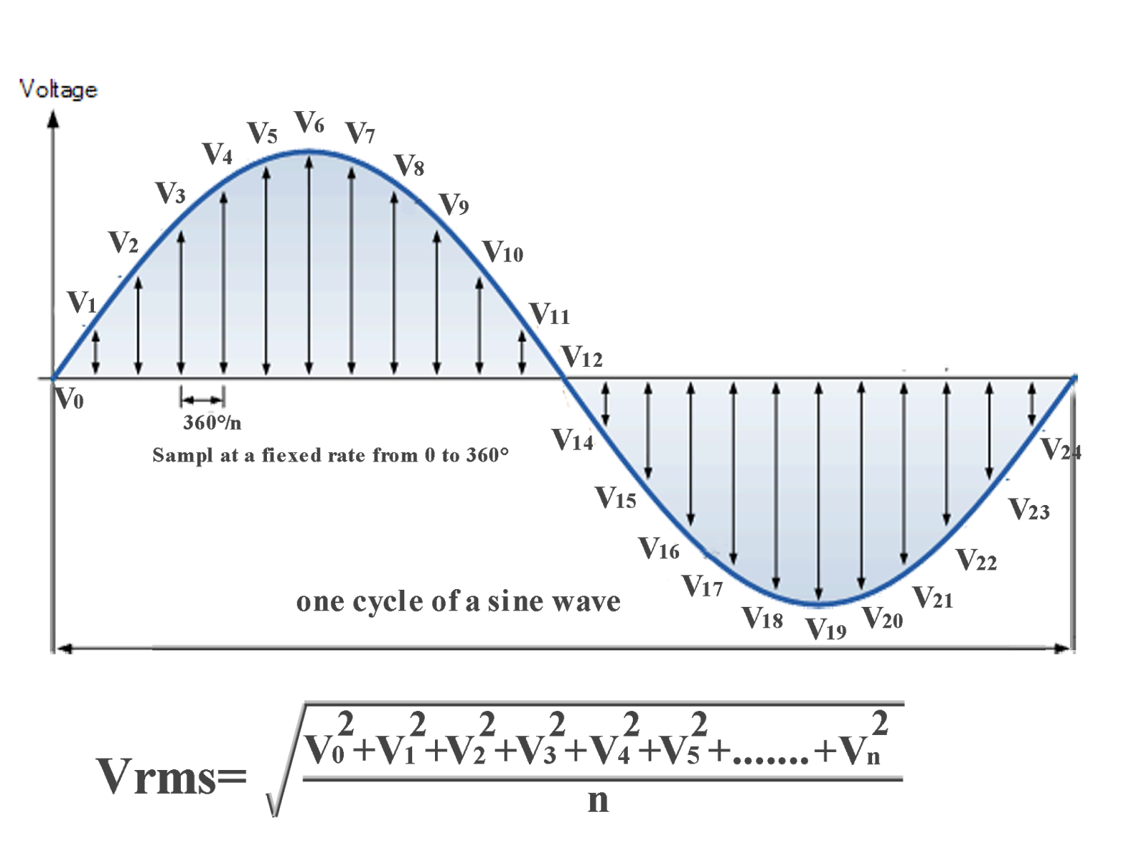
From this, it is clear that an increasing density of voltage sample points across a full oscillation will lead to enhanced accuracy in the RMS value, albeit by a very small degree as one continues to add a high number of samples. If an infinite number of samples is taken within the oscillation, the truly accurate RMS value will be obtained. Of course, in practice, using an infinite number of samples is clearly impossible. However, by calculus, it is possible to obtain the true value using the process of integration.
Integration is a means of finding the exact area between a section of a curve and the horizontal axis for a graph to which one knows the equation. The process can easily be adapted to be of use in truly accurate (not sample-based) RMS voltage calculation: it ascertains towards what true value the RMS voltage tends as the number of samples reaches infinity, thus approaching the true area under the curve between two specified parameters on the horizontal axis. The aspect of area becomes important in Hardware 3.
Since mains voltage takes the form of a sine-wave, its equation can be seen to be:

Where sin(x) refers to a simple sine-wave which simply oscillates between 1 and -1 and where the 325 coefficient increases the amplitude to the real mains voltage level.
Since integrating a graphical function gives the area between the function's curve and the horizontal axis for a specified x-axis range, integrating a standard sine function of the above sort results in the following formula. The parameters T1 and T2 are chosen such that one full oscillation - the period of the function - is selected:

However, the RMS mean is taken not from a standard sine-wave, but using a squared sine-wave - the pattern obtained by squaring each of the "samples" used on the previous page. The equation for a squared sine-wave is therefore:

It is therefore the case that, from this equation, its integral, when taken between time parameters T1 and T2 is as follows:

This formula corresponds to the sum of an infinite number of the aforementioned "voltage samples" - exactly equal to the area along the T1 to T2 range. This integral can be substituted into the sample-based RMS voltage calculation method thus:

Whilst these expressions are mathematically true, in reality, the unit "time" which is assumed in this section for the horizontal (x) axis is somewhat ambiguous. This is because the trigonometric ratio sine requires some kind of angle unit (typically radians - ~6.28 (2pi) radians correspond to 360 degrees, or one full oscillation of the sine graph) in order to produce the expected oscillating pattern. It is therefore the case that a coefficient accounting for angle units (generally radians) and also for the production of a correct frequency is placed in front of x inside the sin function. A mains sine-wave oscillates at 50Hz and will therefore require an x coefficient of ~314 (50x6.28). The addition of such constants for a sine-wave of a particular frequency will correspondingly affect the above expressions, but the overall procedures remain accurate.
[Top of Section] [Top of Page] [Theatre Lighting Contents]
There are various different pieces of electrical hardware which are commonly used in buildings with which it is worthwhile being acquainted. Most simply, one must note that the electricity entering a large building does so along three so-called live wires (or one wire, if a single-phase supply is being used). However, all modern electrical installations have two more wires: the neutral wire and the earth wire.
From GCSE-level physics, one will know that electricity requires a complete loop (through two wires - one entering and one leaving the load) to complete a circuit. In the case of a simple single-phase electrical installation, one of these conductors will be the live wire (on which a voltage, generally 240v, is present) and the other will be the neutral wire, on which there is no voltage but which is essential to complete an electrical circuit in conjunction with the live wire since the electricity (flow of electrons) must be provided with an adequate return path for a complete flow of current.
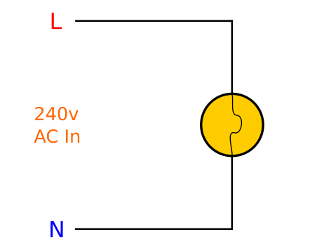
Below is shown a simple single-phase electrical schematic illustrating a connection to a light bulb. The live terminal (red) provides 240v AC power which flows through the circuit, including the light bulb, and returns via the neutral (blue) which is at 0v potential. The AC nature of the supply means that the electric current flows through the circuit from the live terminal in one direction momentarily and next flows through the live terminal momentarily in the opposite direction. This rate of oscillation is 50Hz:
If it were desirable to illuminate more than one light bulb from a single-phase supply, each may be wired in parallel across the live and neutral connection as shown below:
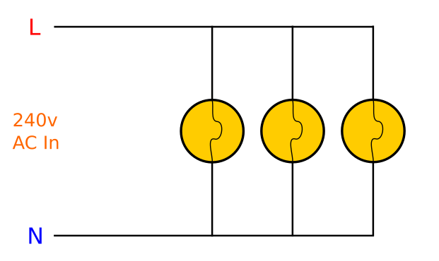
This arrangement means that each bulb receives the full mains voltage and therefore illuminates at its full intensity. This is unlike the effect achieved by placing the three bulbs in series with each other which would result in each one illuminating at one third of its full intensity. In parallel, the branches initially emerging directly from the power source to the point where they link to the leftmost lamp (from the red and blue circles to the first junction) must be rated to carry three times the electrical current of a single bulb: three bulbs are drawing full power through them. For example, if a single bulb is rated at 60W, three bulbs in parallel will require 180W - three times as much power - from the main supply cabling.
One may wonder what sort of a wiring arrangement with regards to the neutral connection is used in a three-phase electrical installation owing to the presence of three live conductors, one for each phase. The answer is that all three phases share the same common neutral connection. This means that the voltage between any one phase and neutral is 240v and a single-phase load can thus be driven with ease if necessary.
One must also note that, in spite of the fact that the three phases and neutral can be used (and indeed most three-phase devices will use the three live wires and a neutral), another arrangement exists where only the three live phase wires are used to drive a load with no neutral. This is commonly used for three-phase motors or heaters and operates as shown in the proceeding picture.
Below: A pair of schematic diagrams of the wiring of a typical three-phase supply (the zig-zag coils represent an electrical load on each phase) in the two aforementioned configurations:

One can see here that, for the latter, right-hand situation, the three phases meet against each other as opposed to all meeting at a common neutral as is the case in the former (shown left). The advantage of this is that less copper need be used for transmission because no neutral conductor is needed and also that the voltage difference between two phases is a higher 415v (see H1.1 - Mains Electricity Theory of Operation) as opposed to the 240v voltage difference between any single phase and neutral as would be the case in the former state. With regards to names, the former standard is known as three-phase star topology, since the wires all meet at a common neutral to form a star shape. The latter, however, is known as three-phase delta topology since the way in which the wires are arranged resembles the Greek capital letter delta.
In addition to the aforementioned neutral wire, all modern electrical installations include one more wire: the earth wire. This is a safety precaution to protect against electric shock should a fault develop on an electrical appliance or installation.
One end of the earth wire is connected to the metal housing of an appliance and the other end is connected physically to the earth (the ground) through the building's structural metal framework (which, just like the neutral, is at 0v potential and thus provides a pathway for complete flow of electricity from any live conductor).
The end of the earth wire which is connected to the appliance's housing is not normally electrically connected to any live terminal since the neutral connection is the primary return path for electric current. However, if a fault develops and a live wire from the appliance's inner workings touches the outer metal casing, this is dangerous since the casing may now become live at mains voltage and could deliver an electric shock if someone touches it: their body provides the electricity with a path to the ground which, as mentioned earlier, is an adequate means of completing an electrical circuit. Therefore, to avoid such a scenario, the earth wire will provide an immediate short-circuit to ground through which a very large current will flow. Such a large current will result in any fuse or circuit breaker instantly cutting off current to the device, thus mitigating any risk of electric shock. Of course, if an appliance does not have any exposed metalwork (for example, if it is encased in plastic), it is said to be double insulated and does not require earthing. An earth connection is required by law on every domestic British power socket.
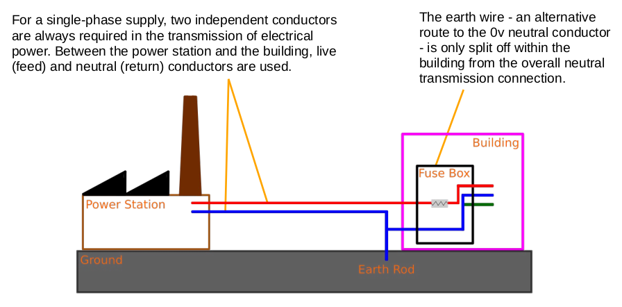
Below: a simplified (excluding electrical sub-stations) single-phase diagram of one of the most common ways in which an electrical supply enters a UK building. One can clearly see here how the single transmission earth/neutral splits to give an earth and a neutral wire downstream of the building's fuse box. Both are at 0v; an earth rod, driven into the ground in the vicinity of the building, ensures that neutral, earth, and the physical ground, are all at the same potential. Blue corresponds to neutral, red to live, and green to earth. A three-phase supply would necessitate three red (live) wires leading to the building:
Below: a comparison diagram showing the purpose of the earth wire in an appliance. Blue corresponds to neutral, red to live, and green to earth. The coil represents the electrical load (i.e. a motor or heater) in the appliance. Appliances with no exposed metal casing typically do not require earthing unless they are likely to come into contact with water:

[Top of Section] [Top of Page] [Theatre Lighting Contents]
Having now explored the general principles of mains electricity and its hardware, one can now focus on the electrical hardware used within buildings and with which the backstage theatre technician will inevitably have to work in order to successfully set up technical lighting equipment.
In most cases, an electrical supply enters a building or venue through a fuse box (also termed a distribution board or, in domestic contexts, a consumer unit). This is generally a covered metal box containing the equipment which splits up the electricity supply into the different circuits found in a building (those for lighting, sockets, electric stoves etc.) and includes protection against short-circuits or over-current faults, such as those described above in H1.2 when discussing earthing.
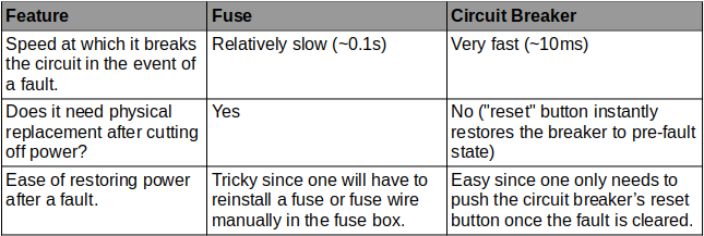
The term fuse box is nowadays something of a misnomer given that most modern electrical installations use electromechanical circuit breakers to protect against over-current faults on particular circuits. Circuit breakers carry out the same task as fuses with a number of advantages:
Inside a fuse box, one will find a main switch so that the user can manually isolate power to all the circuits simultaneously, a row of circuit breakers (each with its own toggle which switches the circuit on and off), and possibly a residual current device (RCD) which may be included to provide certain circuits with extra protection against earth leakage faults (see H1.2) in case a very high-resistance (low-current) fault to earth occurs which does not pass enough current to directly trip a circuit breaker or burn out a fuse.
An individual circuit breaker inside a fuse box typically consists of a rectangular plastic segment with a plastic switch toggle. This switch can be operated manually to control a circuit in a building (for example, a parallel-wired group of 13A square-pin sockets). However, if an over-current or short-circuit fault occurs on this circuit, the switch automatically "trips" to the off position with great speed such that electrical power is isolated from the faulty circuit and the extent of any damage or danger is minimised. The exact current which a circuit breaker can allow before cutting off power is determined by its rating in Amps (A). When installing a breaker, great care must be taken to ensure that the rating is high enough not to prevent rogue tripping from the nominal current draw of the load, but low enough such that dangerously high currents for the circuit's wiring are not allowed for prolonged periods.
A standard circuit breaker is wired "in line" to the live wire leading to a particular circuit - the neutral wire is not intercepted since it is at 0v and it is therefore better to break the circuit by cutting off the high-voltage incoming live wire in the event of a fault.
If a three-phase circuit is to be protected by a breaker, the procedure is exactly the same as above except for the fact that a three-phase circuit breaker, containing three rectangular segments, each with its own toggle, is used to intercept the three live wires leading to the load.
As mentioned in H1.2, the main fuse box is the point where the neutral wire entering a building is split to allow for the use of a protective earth wire inside the premises. After the split, the live wire goes through the relevant circuit breaker(s), the earth wire continues straight to the building’s earthed circuits, whilst the neutral wire, with the live wire, goes through a main residual current device (if present) which detects if any rogue current is leaking through the earth connection by comparing the difference in current between the live and neutral wires: both should be carrying the same “outbound” and “inbound” current if no earth leakage is present.
Below is shown a residual current device which is wired in a fuse box to further protect a group of circuits from any earth leakage faults. Note the fact that, unlike conventional circuit breakers, the live and neutral wires both pass through the RCD; hence the fact that each end has two terminal screws:
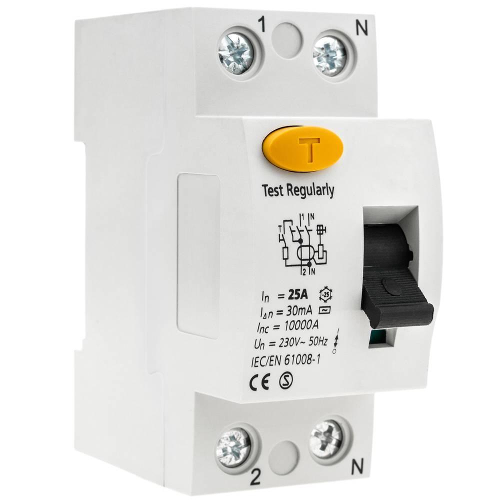
Under normal circumstances, the current through the live wire should exactly equal that returning through the neutral wire - the neutral is the only possible return. If current begins to find alternative "leakage" routes via the earth, not all the current through the live wire now returns via the neutral. The RCD detects this difference and shuts off power.
It is common for a three-phase supply to enter a building's fuse box and for each individual phase to then be assigned its own set of single-phase loads: the phase-neutral voltage is always equal to a standard 240v single-phase mains voltage. This means that the absence of three-phase circuit breakers in a fuse box certainly does not necessarily imply the absence of a three-phase supply.
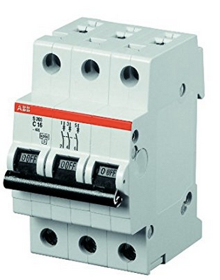
Three-phase breakers may be encountered in a fuse box for fixed three-phase appliances or electrical three-phase socket outlets which are often found in theatres for powering high-current portable devices such as industrial electric heaters. A three-phase circuit breaker is shown below, easily recognisable by the fact that it is three single-phase "segment" circuit breakers with their switch toggles joined together:
It is important that the current draw on each phase in a three-phase installation be as similar as possible to that on each of the other phases since if the phases are unbalanced with regards to their respective electrical loads, the neutral (see the star topology diagram in H1.2) carries a large current whereas if the load on each phase is the same, this "cancels out" the current on the neutral which is desirable to reduce the overall stress on an electrical system. It is also desirable to balance the load on the phases of an electrical supply since power companies will charge extra to buildings which have unbalanced phases because this puts more stress on the workings of their generators and transmission grid.
In older buildings, it is likely that one will encounter a genuine fuse box with ceramic fuses used instead of circuit breakers. Inside a ceramic fuse cartridge is a thin wire which heats up resistively and burns out, thus breaking the circuit, if the current exceeds a certain limit. In most fuses, this wire can be replaced by the user. To do this, the fuse cartridge must be removed and the fastening screws which hold the thin wire in place undone so that the old wire can be removed. Finally, a new piece of fuse wire can be cut (ensuring that it is of the correct current rating as the old fuse wire; the circuit's rating will normally be written on the front of a fuse cartridge) and screwed into the cartridge.
Below: a picture of an old ceramic cartridge fuse:

There exist circuit breakers which can be installed in place of a fuse in a fuse-based fuse box in order to bring the advantages of circuit breakers to older hardware.
In very large electrical installations, it is likely that one will find a number of smaller fuse boxes dotted around the building, from which the building's circuits are then run, owing to the fact that the total number of circuits in such a building would be so large that it would be impractical for them all to be fed from one enormous fuse box.
After the fuse box, electric cables will be run to devices such as electrical socket outlets (single- or three-phase), electric lights, stage lighting dimmers, and dedicated devices such as electric water/room heaters.
With regards to socket outlets, one will likely encounter a few main types of socket/plug in a theatre for lighting purposes. The first, with which one will already be very familiar, is the standard British square-pin plug. This has a maximum current rating of thirteen amps and has a cartridge fuse (not a circuit breaker) inside it. The fuse inside a square-pin plug corresponds to the nominal current draw of the device. Such fuses most commonly come in ratings of 3A, 5A, and 13A and can be changed by removing the back of the plug.
Below: a British square-pin plug shown in its normal state (left) and with its cover removed (right):

The corresponding socket for a British square-pin plug will almost always have a switch to allow easy and safe isolation of appliances and is shown below:
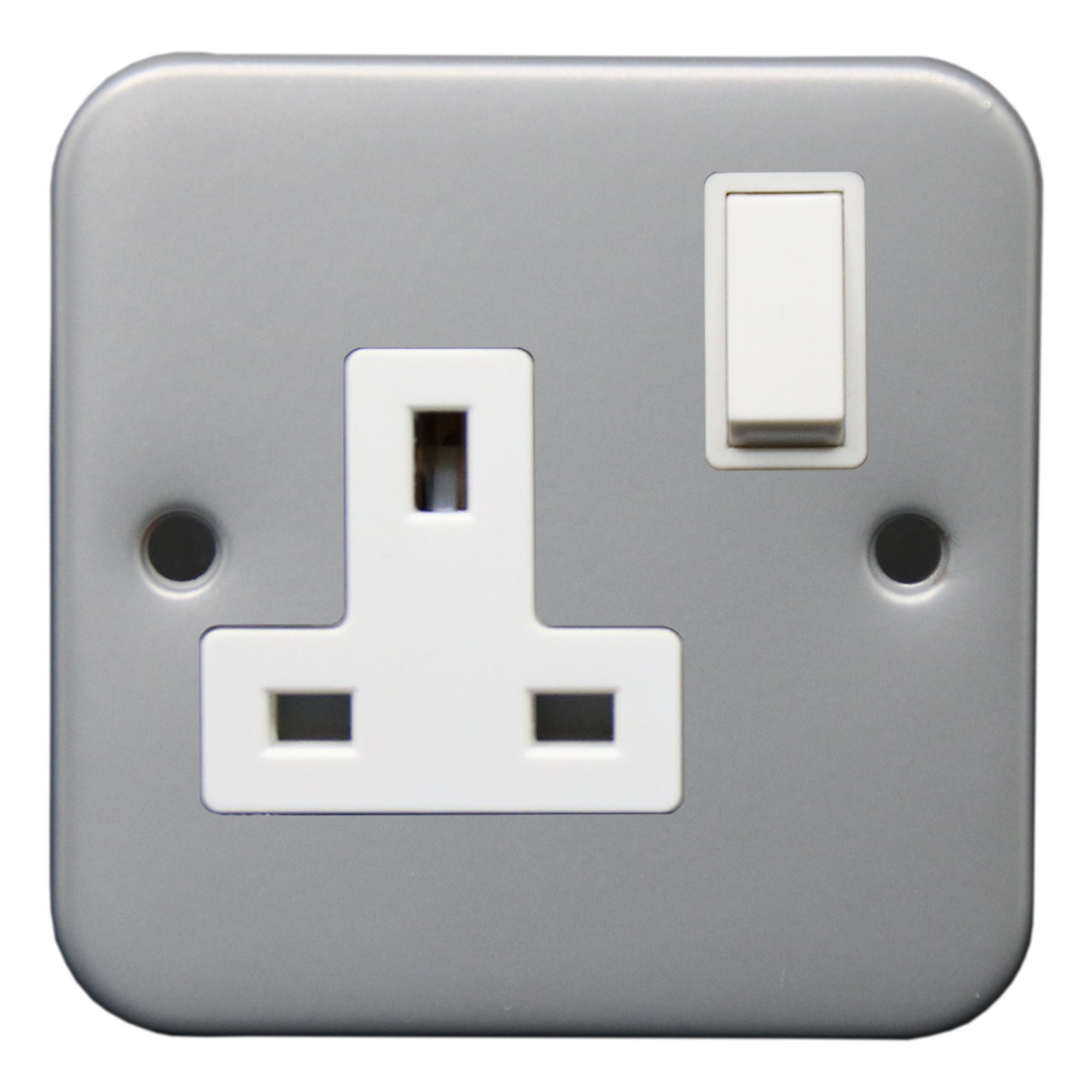
For improved safety, a socket of this sort has internal shutters over the lower two holes -those which are live and neutral - which only open if an earth pin (top hole) is present. This is why the earth pin on a British plug is longer than the other two so that it enters its hole first, thus opening the two lower holes for the other two pins. This means that British plugs, unlike American or European types, always have an earth pin regardless of whether or not the device connected to them is double-insulated and actually needs earthing.
Ordinary, square-pin plugs will be used in almost any theatre or building for general utility power connection points. However, in some very old buildings (pre-1947, when British Standard BS1363 specified the creation of square-pin plugs), one may encounter round-pin plugs and sockets in place of standard square-pin alternatives. These plugs are typically of roughly the same size as a square-pin plug (although, unlike square-pin plugs, there exist smaller variants of round-pin plugs/sockets which have lower current ratings) but are capable of carrying up to 15A of current instead of the 13A maximum of a modern square-pin plug. It is also important to note that round-pin plugs do not contain a fuse and that therefore each round-pin socket in an old building will have its own dedicated fuse at the fuse box, unlike square-pin sockets, parallel-wired groups of which can share a higher-rated fuse/circuit breaker in a fuse box.
In spite of the fact that round-pin plugs are no longer installed instead of square-pin plugs in buildings (although existing installations with round-pin sockets are permitted to continue using them provided they are deemed safe with no clearly hazardous faults), they are still allowed for, and are a standard means of connecting, stage lights to lighting bars/dimmer packs (see Hardware 3: Lighting Dimmers). This is convenient because, in most modern installations, it prevents square-pin appliances being connected to dimmer-modulated stage lighting sockets and any subsequent damage which would ensue.
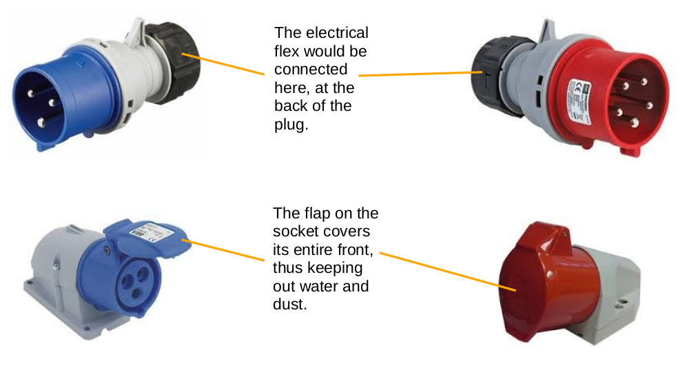
The second type of socket outlet which one will encounter in a theatre is CEEform (commando) connector. This is a more industrial plug/socket arrangement which, unlike ordinary square-pin plugs, is waterproof to IP44 (splashproof) or IP67 (waterproof), can carry a current of up to 800A, and has no fuse in the plug; instead, each socket has its own circuit breaker in the fuse box, with sockets rarely connected in parallel groups. These plugs come in single- or three-phase styles, with the single-phase types being colour-coded blue and the three-phase types being colour-coded red.
CEEform plugs also differ significantly from standard square-pin plugs in the fact that they can come in a variety of physical sizes. The size reflects the plug's maximum current rating, with smaller plugs having a maximum current of 16A and the largest types having the aforementioned maximum current rating of 800A. Single-phase CEEform plugs have three pins (live, neutral, and earth) whereas three-phase CEEform plugs have either five pins (three lives, a neutral, and an earth) if a three-phase star topology is being employed or four pins (three lives and an earth) if a three-phase delta topology is being used instead.
From the point of view of safety, it is worth noting that CEEform sockets do not have the same shutter mechanism as square-pin sockets. Instead of shutters for each hole, a CEEform socket will have a spring-loaded lid over its entire front and which has to be manually pulled open in order to insert a plug. Furthermore, some CEEform plugs have a captive locking ring which is screwed tightly onto the socket once a plug has been inserted; this absolutely prevents the plug from working its way loose.
Below: a single-phase CEEform pair (left) and a three-phase CEEform pair (right):
High-current CEEform connectors are used for connecting devices such as exterior portacabins, lighting dimmer packs, and industrial electric heaters to a building's electricity supply. An example high-current use would be the connection of a touring theatre's lighting dimmers to an electrical system for a few days.
Low-current CEEform connectors typically find use for providing non-dimmed (hot
) power to pieces of apparatus. They are also used in place of 13A plugs/sockets for long cable runs
in potentially harsh environments - where their superior IP rating makes them desirable.
The third connector with which one should be acquainted is the Powercon connector. These connectors have been introduced primarily for use in theatrical devices which plug into standard square-pin (non-dimmed) sockets and which need a suitable connector on the other end of the cable in order to connect to the device itself. One is unlikely to encounter Powercon sockets being used as hard-wired power outlet points in a building, in the same way as would be the case with CEEform and square-pin plugs/sockets.
The main advantage of this connector is that it has a very firm latching action when connecting to the device, meaning that there is no chance of the connector working its way out of its device device over time if located high up on a lighting gantry where it would be a nuisance to reconnect.
Below: a Powercon plug (right) and socket (left). The socket would typically be on the device to which the plug provides power:

In order to connect this type of connector, the plug is inserted into the socket and twisted clockwise until it latches with a distinct click. To disconnect, the catch is pulled back and the plug is twisted anticlockwise until it comes free from the device.
Powercon connectors are not waterproof and have a maximum current rating of 20A. Some variants may claim higher currents but may require proprietary sockets to fulfil this. The most common use for these connectors is to connect devices such as smoke machines or LED theatre lights - which are not powered from a dimmer pack - to the standard constant mains electricity supply.
A final useful connector in theatrical lighting contexts is the Socapex connector:
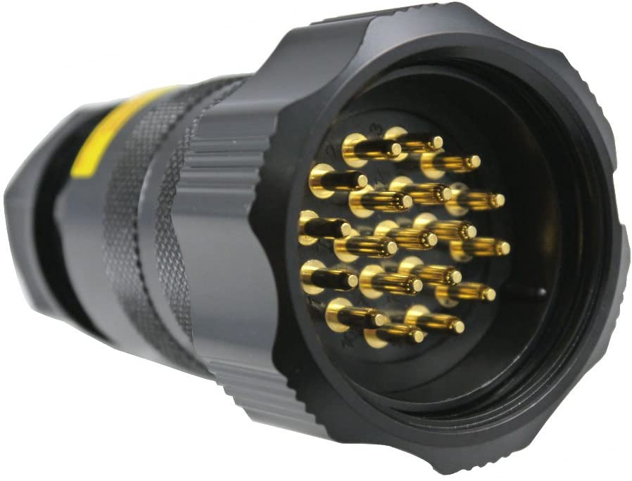
Socapex provides a useful means of connecting six separate power supply lines - each consisting of a live, a neutral, and an earth wire - as one connector. A multi-core cable is used between Socapex connectors; this allows for the six separate power supply lines to run neatly as a group over a given distance.
It is sometimes the case that a six-channel lighting dimmer pack, or power distribution unit more generally, will provide its six outputs by means of a single Socapex connector on the front panel. This means that one end of a Socapex cable can be used to neatly connect all of the pack's outputs simultaneously. On the other end of the same cable, a 6-way splitter would typically be used to convert the grouped Socapex power connection to individual trailing sockets into which stage lights, or other powered equipment, may be connected.
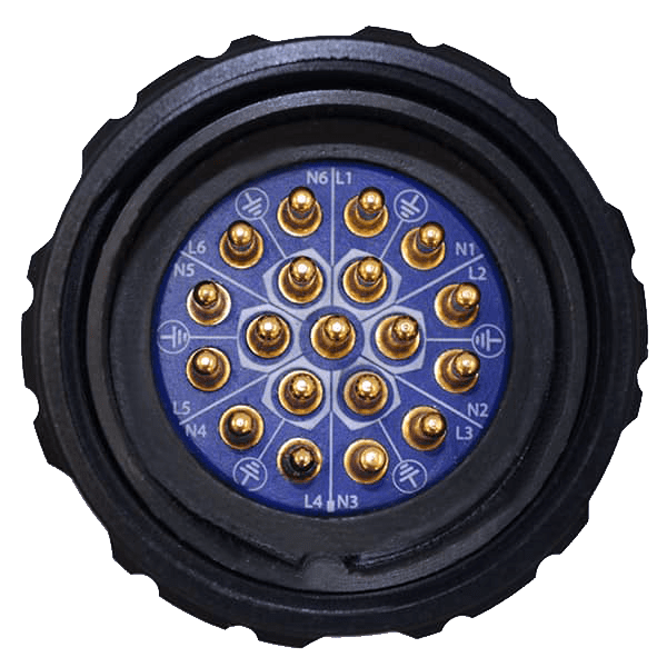
Below: a close-up of a Socapex connector. The pins of this particular connector are labelled to show their function. Essentially, there are six groups of three pins (live, neutral, and earth) - one for each power supply line - arranged in a circle around the edge of the connector. Note that the centre pin is unused.
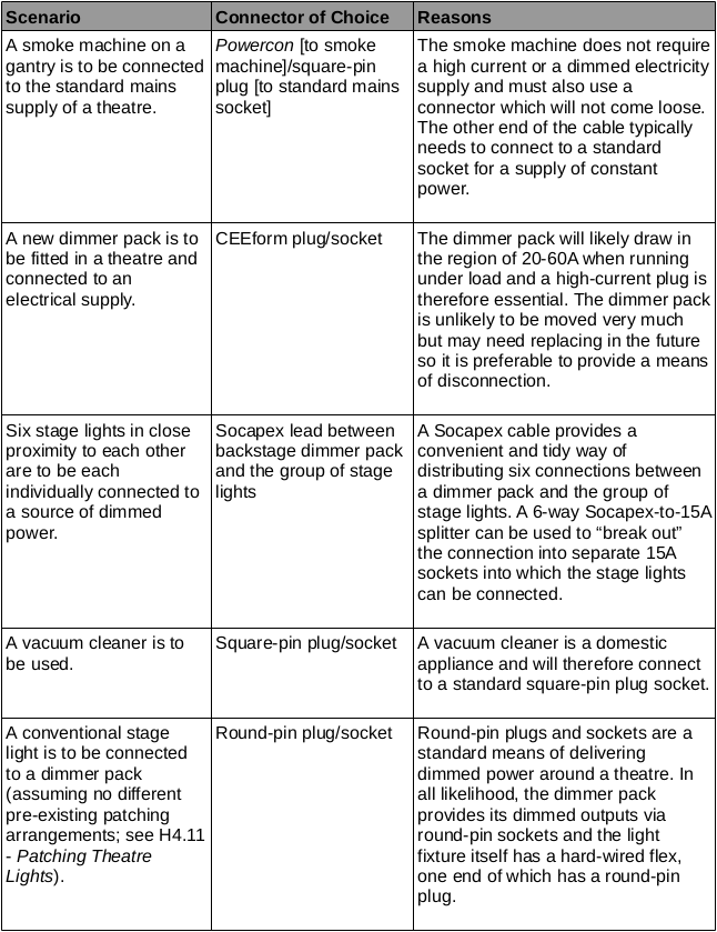
To round off this section about some common electrical connectors, a table of example scenarios is given below:
