Cordless Phone Walkie-Talkies - 20/05/19
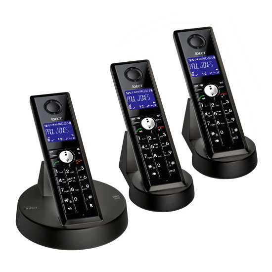
Cordless telephones operate on much the same principle as conventional walkie talkies: analogue vocal signals are converted into (generally digital) radio signals which travel over long distances. It is therefore possible to modify a set of three cordless telephones to work as a two-way radio (i.e. a pair of walkie-talkies). This process is further faciliteted by the fact that sets of three cordless telephones, such as that shown below, have an "intercom" facility by means of which one handset of the trio may call another one and have a converastion - a physical external telephone line is not needed for this.
Below: a set of three cordless telephones, such as the one I used. This project used the two "extra" handsets (the two rightmost ones in this picture). The leftmost handset and its base were dismantled to make the linking transmitter (see below):

For this Project, I used the two extra handsets from a set of three cordless telephones as my walkie-talkies. However, in order to link the two extra handsets together, it is necessary that the main base station be powered up and active because this links the handsets together and allows for a local intercom call to be placed. The miniature bases from the two extra handsets can be used to keep them charged up.
Below: the two extra handsets which I chose too use for my project:

Bearing in mind that I wanted this project to be portable and that the main base needs to be constantly powered for the phones to be linked, I needed to be able to power the base from a battery pack. I therefore cut the wire to it from the power supply and spliced on a 6v battery pack (this provides the same voltage as the original power brick) so that the base station, and therefore the two walkie-talkie, handsets could be carried about and still used in the absence of mains power. Below you can see a picture of the base when I had completed this:

After having tested this initial setup, I then removed the circuit board from the main base and kept the handset from the main base as a spare (the two extra handsets are used for the walkie-talkies). I put the circuit board inside a PVC project box with a screw-on top along with the battery pack so that it is easily portable and protected. I also added a 6v DC input jack to allow for the possible connection to the mains if desired. The user can choose between operating off the batteries or from the DC input jack by means of a front S.P.D.T switch.
Below: the schematic diagram for the switching circuit which allows the linking transmitter to run either off a DC input or off a 6v battery pack:

Below: the circuit board, batteries, DC jack (with DC cord plugged into it), and switch (bottom left) installed in the project case for use as the aforementioned linking transmitter:

Once I had checked that this setup was working, I fitted the lid and tested the link between the telephones and this linking transmitter.
Below: the linking transmitter box with its lid fitted. This photograph is taken with the switch and DC jack in clear view:
