Custom Garden Lighting Circuit - 17/02/19
This project arose out of a need for me to provide reliable lighting to a remote corner of my garden: it is too far back for the house's outside light to illuminate it and is too sheltered by trees for the use of solar path lights.
I also wanted this system to operate off of one standard low voltage for it to be safe outdoors in a potentially wet environment. I also wanted the system not to rely on batteries since I thought that this might prove unreliable and expensive.
While beginning the initial surveillance for this project, it also ocurred to me that it would be worthwhile to install an electricity supply to a shed which I built for storage of old computers in the same remote corner of the garden so that the light inside it could also run off of the aforementioned low-voltage supply, thus eliminating the present need for batteries to power the shed's lights.
I began by deciding on what voltage I should run the system. I settled on 12v since I knew that I could obtain this from a high-wattage ATX power supply and I also had a pair of 12v spotlights salvaged from an emergency lighting module in conjunction with a 12v fluorescent lighting lamp module, all of which I could use to illuminate the path.
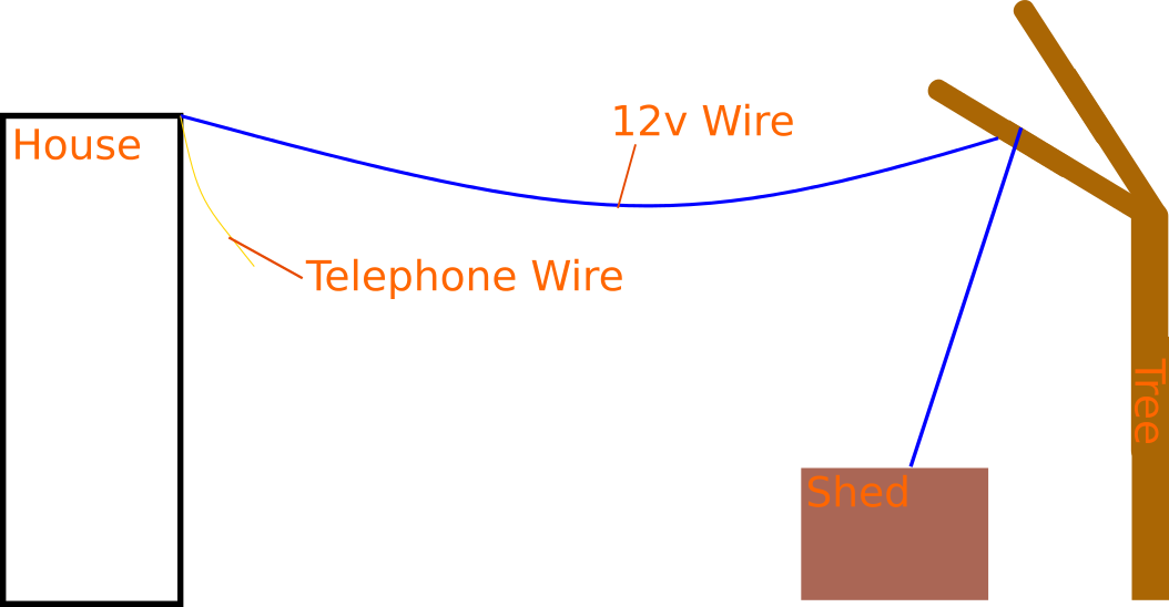
With the voltage having been decided, I set up an ATX computer PSU in a cupboard under an upstairs window inside the house. This meant that I could connect a long cable to the 12v rail of this PSU, run it through a hole in the sill of the aforementioned window through which my telephone line also runs, and drape it across the garden (in the air) between this window and one of the tall trees above my old shed (i.e.: the corner of the garden which needed illumination).
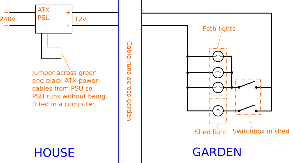
NB: When re-purposing an old ATX power supply such as I did, one must bridge the green wire on the main ATX motherboard connector to another black wire on the same connector in order to ensure that the power supply starts up when plugged in (this would normally be handled by a computer motherboard and is how a computer tells a power supply to start when the power button is pushed).
Below is a simplified cabling layout from the house to the corner of the garden:

When I had secured the cable to the tree by wrapping it around a branch and pulled it tight, I successfully checked it for continuity by connecting my multimeter to one end of it in the garden and applying power to the ATX computer PSU in the house. Next, I screwed my two 12v tungsten spotlights onto two different trees in the remote corner of the garden along the path which I wanted to illuminate. I also screwed the fluorescent lighting module even further down the path on a fence post.
Concerning cables to the above, I first dropped the main 12v cable from the house down from the tree into the small shed; I wanted to power the existing shed light from the new 12v supply and also to place my switchbox for all the lights in this shed. I then took a new cable out of the top of the shed and draped it (high up) to the first tree on which a spotlight had been mounted. I then connected this to the spotlight using terminal blocks and led another cable from this tree to the second one which had a spotlight in a similar manner to before and connected this one as well. From this second tree. I then ran a longer wire further down the fence using several cable grips and connected this to the fluorescent light on the fence post. The way in which I daisy-chained the lights means that they would all be wired in parallel and therefore receive the full 12v each.
Below: a picture of a spotlight on a tree:

Below: the fluorescent light on the fence:

Finally, I mounted two toggle switches into the front of a new PVC project box, one switch for the shed light and the other for the path lights, and drilled two final holes in the sides of this box through which I could route all the necessary wires. I then went back into the garden and installed this box in the shed and connected up the cables as is shown by the following schematic of the overall finished system.

Below is the finished switchbox mounted to the inside of the shed:
