Alternative Uses for a Fluorescent Starter - 15/03/16
Fluorescent lighting is commonplace in a multitude of buildings from offices to homes and schools; yet the working of fluorescent tubes and fluorescent fittings is far less widely understood than that of incandescent light bulbs and somewhat understandably owing to their comparatively complex workings.
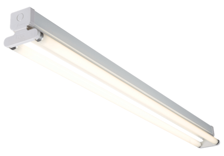
Below is shown a common twin-tube fluorescent fitting:

All fluorescent fittings contain these basic components:
The purpose of the fluorescent starter is to provide momentary power to two filaments located at either end of the tube which emit electrons into it and help to heat and raise the mercury vapour which is what gives out the light which one sees from a fluorescent tube. Another important point is that the starter needs to shut off power to the two filaments once the tube has lit and it also needs to re-engage should the tube require another burst of preheating to start it, this is the reason for which many fluorescent fittings flicker when starting, for the starter is rapidly engaging and dis-engaging until the tube has fully lit and warmed up. It is crucial that the starter does not run the filaments for longer than is necessary owing to the fact that running the filaments puts unnecessary strain upon the ballast and may cause it to overheat.
So, how do they work? When power is first applied to the fitting (i.e. when the light switch is turned on), the voltage across the tube is high enough, since it is not alight and drawing current, that the starter engages and turns on the two filaments which start to preheat the tube; once the filaments turn on the tube will light (perhaps momentarily) and, if it remains lit, then the voltage across it is too low, with current now passing through the mercury arc discharge, to trigger the starter again but, if the tube fails to stay lit (i.e. if it flickers on, then off again), then the voltage across it will rise, the starter will engage and the operation will repeat until the tube has, and remains, lit.
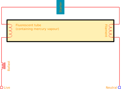
This diagram shows the typical wiring of the ballast/tube/starter in a fluorescent fitting:

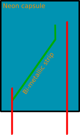
Inside a fluorescent starter are two electrodes, between which is placed a bi-betallic strip. Both the electrodes and the bimetallic strip are in a glass capsule containing neon gas. When the starter engages, (i.e. When the voltage across the tube is high just after power-up) a neon glow discharge occurs within the glass cpasule. This small glow in turn heats the bimetallic strip and causes it to bend and bridge together the two electrodes, thus engaging the two small end-of-tube filaments and also bypassing the neon gas. With the neon discharge now bypassed and stopped, the bimetallic strip begins to cool. It bends back to its original position, disconnecting the end-of-tube filaments from power and effectively applying mains voltage across the length of the tube. At this point the tube flickers/lights. If the tube lights, then the voltage across it stays low so the neon in the starter can no-longer begin another glow discharge, but if the tube only briefly flickers, the cycle will repeat itself until the tube has lit, at which point the starter stays dis-engaged until next required.
Below you see a diagram of the inner workings of a fluorescent starter:

NB: For these experiments, I used a DC bench power supply which could provide high voltage (>125v for the starter) with sufficient current to drive the starter. It is alternatively possible to use a mains connection, but this (at least in 240v countries) is more dangerous. I also used a simple 240v 60w GLS bulb.
Returning to the title of this article, fluorescent starters do not have to be used with a fluorescent tube but can be used with an ordinary incandescent light bulb. When first wired up in series with an incandescent bulb, the voltage across the bulb is high so the neon in the starter begins to glow, the bimetallic strip then engages, turns on the light bulb, and dis-engages the neon. The bimetallic strip will then cool down and move to its original position, turn off the light bulb and the neon will begin to glow again. This cycle will repeat continuously making the light-bulb rapidly turn on and off in a random rapid flicker.
Using two or three starter-driven incandescent light bulbs simultaneously creates a very nice fireplace
effect, with a continuous,
fully-random flicker such as that which would emerge from a genuine log fire. This arrangement can sometimes be used
very successfully for theatrical purposes.
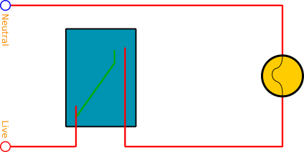
The below schematic shows how a fluorescent starter can be connected in series with a filament lamp:

Below is my physical implementation of the above circuit, connected to a mains plug:
Another more risky use of a fluorescent starter is as a miniature neon lamp. This involves connecting a resistor in series with the starter to limit the current to it and thus prevent the intensity of the neon discharge from ever getting hot enough for the bimetallic strip to bend and bridge the two electrodes. However, getting the right value of resistor is paramount because an under-rated resistor would still allow enough current to pass for the starter's bimetallic strip to engage, effectively shorting out the neon and putting too much current through the resistor which could cause it to overheat, and, in some severe cases to catch fire.
Here is what happened to a resistor when I chose the incorrent value and the starter's bimetallic strip bent over and bridged the two electrodes, effectively short-circuiting it directly across the supply: