Basic Introduction to Networking Infrastructure - 03/04/2024
For both hobbyist and professional applications, I regularly find myself configuring a wide variety of network switches, wireless access points, routers, and other pieces of computer network infrastructure. I have therefore put together this guide to serve as a basic introductory reference to the different pieces of essential modern networking equipment. Very little prior knowledge is assumed.
All devices which can be networked together need a set of shared rules (a language
) which they can use to
communicate (talk
) to each other. This set of rules is referred to as a protocol. It is very important that all
connected devices on a given network share (speak
) the same protocol (language
). For the purposes of
internet-related networking, the vast majority of consumer hardware uses the Ethernet protocol.
The protocol is generally an independent standard compared to the wires used to physically interlink devices. That is to say: the presence of a certain physical connector on a piece of hardware does not imply the use of a particular protocol, because different cables can often carry different protocols in different circumstances. For the purposes of networking training, most devices which support the Ethernet networking protocol generally have the following illustration etched somewhere on their I/O panel(s):
[Top of Page] [Networking Guide Contents]
Cat5(e): Most cables which are used nowadays to wire up networks are Cat5, or the enhanced
Cat5e
equivalent. This type of cable has plastic end connectors, 8 internal pairs of copper cores, and (occasionally) foil
sheathing to protect the cores from external electromagnetic interference. These cables are usually very reliable,
but general-purpose Cat5 is not the most robust, so can sometimes be the cause of dodgy data connections,
particularly if the immediate environment is especially harsh.
Below is shown a Cat5 cable (left) and socket (right):


Ethercon: The damage risk associated with regular Cat5 can be mitigated by using Ethercon cables, which have additional mechanical shielding around the cable and connectors. These are very common for networked infrastructure intended for touring use (e.g. live events).
Below is shown an Ethercon cable (left) and socket (right). Note how the outer plug sheath closely resembles that of an XLR connector.
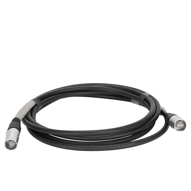
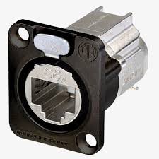
Whilst regular Cat5 connectors will happily fit into Ethercon sockets, the same is not true in reverse. The sheathing around Ethercon connectors means that they must be connected to dedicated ports. Most high-end network-connected equipment (e.g. Dante sound mixers) intended for use in theatre / live events ships with Ethercon ports to give maximum cable compatibility. Inline Ethercon couplers can be used to link Ethercon cabling to regular Cat5 lines.
NB: Any cable can effectively transmit any type of signal/protocol. Cat5e cables are principally used for networking together computers, but can be used to transmit many other non-network-related signals/protocols, such as analogue video or audio, if the correct adapters are used. When connecting together networked devices, care must therefore be taken to ensure that, even if they all appear to have Cat5 connectors, they are all actually communicating over Ethernet - the decades-old standard used by internet-connected devices – rather than simply using those same connectors for a completely different underlying signal.
[Top of Page] [Networking Guide Contents]
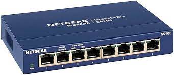
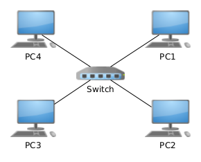
Most Ethernet networks essentially follow a star topology. In this topology, all devices connect back to a central connection point of some description. This central connection point mediates communication between all its devices. In the case of Ethernet networks, the role of a central connection point is fulfilled by a switch. A switch is nowadays one of the most fundamental and important pieces of networking hardware.
Below: A common 8-port home/small-office Netgear Ethernet switch (left) and an enterprise-grade 48-port Cisco switch (right). The latter variety would frequently be used, for example, for connecting up an entire office block's worth of PCs:

The most elementary type of Ethernet network consists of a set of Ethernet-enabled devices (e.g. laptops/ desktops/printers) connected to a central switch via Cat5/Ethercon cables. In this configuration, multiple devices on the switch can talk to each other - the primary goal of any network.
Below: An example star network topology. All devices connect to a central switch, which allows them to communicate with one another:
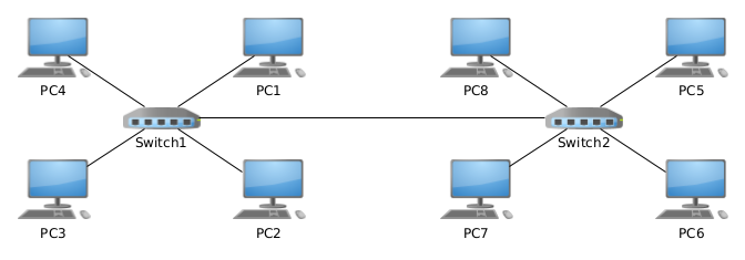
Network switches can be daisy-chained. This means that two switches can be connected together by linking
a port on each switch. This inter-switch connection is commonly referred to as an uplink. In effect, this
doubles the number of switch ports available for connecting devices together. This configuration additionally
carries the advantage of allowing the two switches to be geographically separate from one another, effectively
creating two conjoined network segments
linked by a single cable.
[Top of Page] [Networking Guide Contents]
So far, the network principles described have been orientated around wired connections: an Ethernet (Cat5/Ethercon) cable linking all devices to a central switch. Obviously, however, wireless network access is possible. In home/office settings, this type of access (branded WiFi) is most commonly encountered for the sake of convenience, as a means of connecting portable devices to a network.
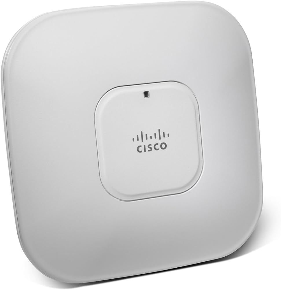
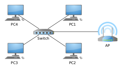
The device which permits wireless network connectivity is known as an Access Point (AP). This may be thought of as a unit which takes a wired connection from a switch (as discussed above), and uses internal radio antennas to make this connection accessible to wireless devices. As far as the network switch(es) is concerned, the AP effectively simply appears to it as another regular Ethernet-connected device.
Below: A common wireless AP from Cisco:
Rather than plugging in a Cat5 cable to a piece of hardware, the connection process for linking (associating,
in WiFi terminology) a wireless-capable device (client, in WiFi terminology) with an AP involves using
client-side software to tell the device to which AP it should connect its radio antenna. Each AP is identified
by a unique user-defined wireless network name (Service-Set Identifier, or SSID
, in WiFi terminology).
A password must then often be entered; this provides security to prevent unauthorised client devices linking to any
AP. Once these steps have successfully been completed, the device can then access the network just as if it were
connected with a direct Cat5 cable.
Below: the network from Section 2, with an added AP:
[Top of Page] [Networking Guide Contents]
Originally developed by Cisco for powering VoIP (Voice over Internet Protocol) phone handsets, PoE allows
wired network devices such as APs, internet-connected CCTV cameras, and IP telephones, to derive power,
as well as network connectivity, from a central switch. This eliminates the need to supply certain devices
with power from a local plug/battery. Not all network appliances support PoE, by any means: the main use of
this feature is for smaller permanently-installed appliances, such as APs or CCTV cameras. Likewise, not all
network switches are capable of supplying PoE. Thankfully, PoE-capable switches are clever enough to automatically
negotiate
which of their connected devices can and can't receive PoE, and only activate PoE for supported
connections. It is therefore perfectly safe to connect a non-PoE-capable device (e.g. a desktop computer) to a
PoE switch: it simply won't make use of that element of the switch's functionality.
[Top of Page] [Networking Guide Contents]
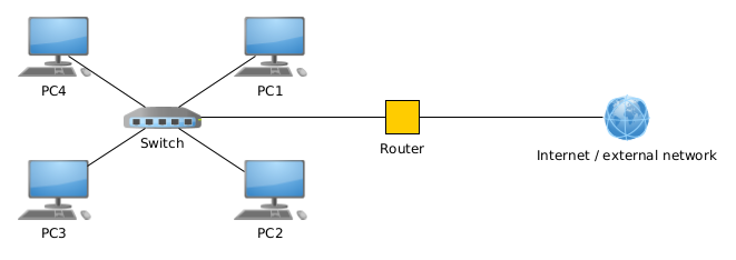
For all intents and purposes, a router provides a means of linking networks to one another. Consider
the star
topology exemplified in Section 2: The devices can all communicate with each other through the
switch, but no communications can travel beyond the switch. By connecting a router between a spare switch
port and another external network connection, it mediates access between the switch's network - from now on
referred to as a Local Area Network (LAN) - and another, external, higher-level, connection - from now
on referred to as a Wide Area Network (WAN). In most IT cases, this higher-level external WAN link
takes the form of an internet connection. Therefore, in such cases, a router acts as a bridge
between a
local network and the wider global internet.
Below: an illustration of a router's role in linking the switched network from Section 2 to a wider external
internet connection. The router has one outward-facing
(WAN) network port, connected to the internet, and
another inward-facing
(LAN) network port, connected to the local switch. Access from the local network out
to the internet, and vice versa, is closely mediated:
Technically, this mediation
is the duty of a firewall rather than a router; but for all intents and
purposes, and for all but the largest corporate networks, firewall duties are integrated into a router.
In the vast majority of cases, routers provide welcome segregation between networks. This has clear security
benefits. For example, a street of houses often all receive broadband from the same provider (Virgin Media, BT, etc.).
That is to say, each house receives a connection to the provider's country-wide network. However, because each house is
supplied with a local router at the point where the internet connection enters the building, a user's PC at Number 5
cannot communicate with the smart doorbell in Number 6. Furthermore, as far as the broadband provider is concerned,
each house only has a single device - its router - connected up to their service from the street: the provider only
sees
the router's external-facing link; all LAN devices within the house can connect out to the internet,
but are masqueraded
from wider view. For more detail about the constituent parts of a home router, see below.
Finally, a router is more often than not responsible for allocating unique identifications (IP addresses) to all devices on its local network. However, this is not an essential duty, by any means, because unique device identification can be carried out perfectly well on a small network in the absence of a router if things are suitably configured.
[Top of Page] [Networking Guide Contents]
This is a term which I rather dislike, but which seems to have been adopted in one form or another by most major
British broadband providers (BT, Sky, Virgin Media, and Plusnet, all seem to use it) as a way of referring to
the box
they supply with their home broadband packages. Most people nowadays regard such a box as something
of a life-support system for the entire household.
A more accurate term for a hub
, would be combined router, network switch, and wireless access point
,
which is exactly what a hub
consists of, under the hood. The external connection from the broadband
provider first passes through a router, which mediates connections between local (LAN) devices and the
outside internet, as well as ensuring that all the local devices in the house can communicate with each other
properly. Next, the connection enters a switch, which serves to bring out multiple local Ethernet ports on the
back of the hub
. Finally, the aforementioned Ethernet switch is also bridged to a small internal WiFi AP. This
provides the WiFi network to which portable devices may be connected.
Consider the basic star network topology in Section 2. So far, we have established that all devices must be connected to a switch in order to talk to one another, and that device-switch connection can take the form of either a direct Cat5 Ethernet cable or a wireless link by means of an AP. However, client devices sharing a local network require some kind of identification, both per-device and per-network: each device must be able to identify itself uniquely in order to know which messages to listen out for, and where to send messages if it wishes to communicate with something else. Furthermore, it is often desirable, though not entirely essential, to have a means of identifying the network as a whole. These identification methods should be configurable on a network-by-network basis.
Enter Internet Protocol (IP) addresses. An IP address is a unique identification code assigned to every device on a network. IP addresses consist of four groups of 8-bit numbers, termed octets. For example, a computer connected to the network from Section 2 might have an IP address that looks something like this:
In this case, each dot-separated string of digits represents a single octet (8-bit binary number). Another device on the same network might have an IP address as follows:
For a given LAN, a certain number of left-hand octets form the network ID. This means that, for all devices on the network, this portion of their IP addresses is always the same. In the case of the above example IP addresses, the first three octets of the IP addresses remain constant, with only the final octet changing value based on the device. The first three octets, in this case, therefore form the network ID. The final octet(s) which change value per-device, are termed the device ID. The combined network ID and device ID form a full IP address.
This begs the question: how do we know how many octets are allocated to the device ID vs. how many octets are allocated to the network ID? This final piece of the puzzle is solved if we consider the concept of a subnet mask. A subnet mask may be regarded as a special per-network code which identifies, for that particular LAN, how many octets of the network's IP addresses are the network ID. A subnet mask for our example network would look like this:
As we can see, the mask also consists of four octets. However, each octet is either 255 (i.e. the maximum value representable with 8 binary bits) or 0 (i.e. the minimum value representable with 8 binary bits). How to use the subnet mask to calculate the network ID from any given IP address is best illustrated by writing the mask above the IP address:
From this representation, one can see that any octet from the IP address which falls underneath a "255" octet in the subnet mask is part of the network ID. Conversely, any octet from the IP address which falls underneath a "0" subnet mask octet is part of the device ID. By performing analysis of this kind, network-connected devices, when presented with any IP address and subnet mask, can extract the device and network IDs.
Please note that this explanation of subnet masking, whilst representative of the technique used in real networks, is slightly simplified for the purposes of this article. It is also perfectly sufficient for the vast majority of networks which one is likely to encounter in the field. If interested, for a more factually detailed explanation of real subnet masks, see the Wikipedia article.
With regards to allocation of IP addresses between network-connected devices: there are two main methods of achieving this, depending on the network size and complexity.
The first method is known as static assignment. In this case, each device connected to a local network is
manually configured with an IP address and subnet mask. If a router is present on the network, a router (gateway
)
address is also manually specified, so that the device knows where to send communications aimed at the wider upstream
network. An obvious disadvantage of this method is the administrative burden: devices must be manually configured and
the administrator needs to keep track of all the statically assigned addresses to make sure that no two devices are
accidentally assigned the same one - something which would, in effect, make them talk over each other
. Clearly,
this method is entirely unsuitable for networks of any remotely appreciable size.
The second method, known as dynamic assignment, presupposes the presence of a router on the network - a perfectly reasonable assumption for a LAN of any medium-to-large size. This method levereges the Dynamic Host Configuration Protocol (DHCP). DHCP allows a central DHCP server (generally residing on the router) to allocate IP addresses to all client devices on the LAN. Instead of setting IP addresses and subnets manually on each device, they are simply instructed to listen to the DHCP server in order to obtain their IP addressing information. The router's on-board DHCP server maintains a record of all IP addresses allocated to the different network devices and monitors the network for any signs of newly connected devices. If a new device is detected, the router's DHCP server selects an unused address and allocates it to the device. The device then uses this address for its communications until instructed otherwise by the router.
It is worth noting that IP addressing schemes differ greatly between LANs, and that a device with a certain IP address on one network will likely acquire a totally different address if connected to some other LAN, especially if DHCP is involved. Most home networks have a 192.168.1.xxx IP addressing arrangement (subnet mask 255.255.255.0), meaning that the first three address octets are the local network ID, and the final octet is the device ID. Owing to the limitations of 8-bit numbers, however, this scheme has a limit of 256 unique IP addresses (i.e. the maximum number of unique forms which the final octet can take, given that the first three octets are fixed as that network's ID). Whilst a limit of 256 devices is perfectly acceptable for most domestic settings - any home users with more than 256 devices should be capable of setting up their own alternative networking arrangements - institutions with many networked devices will often employ LAN addressing schemes with subnet masks of 255.255.0.0 or less, massively increasing the number of available device IDs.
One final note: In the case of the 192.168.1.xxx network, I deliberately said 256 unique addresses
,
rather than 256 unique devices
. This is because, whilst in the majority of cases, each IP address does equate to one
device, there is an exception: the xxx.xxx.xxx.255 (assuming 255.255.255.0 subnet mask) address is known as the
broadcast address, and is a special address which can be used by any network client device to send traffic to all
LAN devices at once. This is of great use for certain services such as DHCP, when communications need to be sent to all
network devices at once, and saves a great deal of resource capacity compared with repeatedly distributing the same message
to all individual device IP addresses consecutively. The caveat, however, is that use of the broadcast address can cause
considerable network congestion, particularly in certain wireless network configurations.
Whilst this type of address typically requires little configuration involvement from a technician, it is still useful to know about. In essence, a MAC address is a globally unique identification code hard-coded into the interface(s) of any network-connected device. This helps to identify network devices when they are first connected to a given network.
When expressed in their usual (hexadecimal) form, MAC addresses have the following appearance:
Where X represents a hexadecimal digit (0-9,A-F)
[Top of Page] [Networking Guide Contents]
An integral part of any institutional IT system, VLANs allow for logical segregation of a local LAN topology into smaller isolated regions, without the need for physically separate switch hardware. VLANs are typically only supported on enterprise-grade switch hardware. In essence, enabling VLANs on a supported switch allows different banks of its ports to behave as though they were entirely isolated "mini-switches". For example, computers connected to ports 1-12 of a switch may be entirely separated from computers on ports 13-24. In very large networks, this is a great benefit, as it reduces the amount of traffic which ends up reaching all network endpoints, in turn regulating network congestion and improving security.
A classic example of a VLAN use-case would be in a school building: computers in the ICT room might be put on their own VLAN, with access to each other and shared pupil resources (e.g. file/logon servers). On the other hand, teachers' classroom PCs might be assigned an entirely separate VLAN, with access to potentially more confidential resources within the school network. Even if they're implemented on the same building-wide switch, the two VLANs (banks of isolated switch ports) are more or less entirely isolated from each other.
[Top of Page] [Networking Guide Contents]
This is an incredibly complex topic, and there exist numerous ways of building fault-tolerance into network designs. I will therefore only touch briefly upon one of the most basic fault-tolerance systems used on switched LANs: Spanning-Tree Protocol (STP).
Consider the second, dual-switch, topology illustrated in Section 2: the two network switches are linked by one single network cable (uplink). If this inter-switch link were to fail (broken cable, accidental cable removal, etc.), the two network zones would be unable to communicate with each other.
To add some level of redundancy, we might add a second inter-switch uplink. That way, if one link fails, there's still another one to fall back on. However, with basic switches in their standard configuration: duplicate links between switches do not work. Duplicate links directly between switches give rise to a broadcast storm. This means that the redundant links form a loop in which network traffic continues circulating indefinitely. This rapidly saturates both links (and possibly both switches in their entirety) and renders the network inoperable.
Avoidance of link duplication whilst retaining redundancy is the core role of STP. STP allows for provision of duplicate links between (groups of) switches, whilst avoiding the aforementioned broadcast storms. STP is typically enabled in software within a suitably sophisticated switch. In normal operation, STP works by shutting down superfluous inter-switch links. Only if a given link fails is another duplicate automatically enabled in a "failover" fashion, maintaining inter-switch connectivity.
[Top of Page] [Networking Guide Contents]
This system is what allows IP addresses to be referenced by human-readable strings of text, called hostnames, such as are found in web addresses. DNS-capable networks contain a DNS server. Like a DHCP server, in small networks, this is often part of the central router. The DNS server maintains a copy of the hostname of each network-connected device, matched up with the device's corresponding IP address. When a certain device (e.g. a user's PC) wishes to access another network resource (e.g. a printer/server), the user may either enter the target IP address directly (but this isn't very memorable) or instead enter a human-friendly target hostname. In the latter case, this hostname is sent off to the DNS server, which returns the matching IP address. The original device then uses this IP address to initiate a connection, just as if the user had entered it directly.
One of DNS's key features is the fact that is is recursive. This means that hostname requests can be forwarded from one server to another in a hierarchical fashion. On the wider internet, which may simply be regarded as one enormous network, this method is what allows web addresses to be resolved: a web server has a numerical IP address, accessible across the whole internet, and a DNS record (on some public DNS server) pointing to this IP address. Queries from website visitors are forwarded between public DNS servers until a matching hostname record (i.e. the bit of the web address after http://) is found.